Create Hub Profile for first Hub
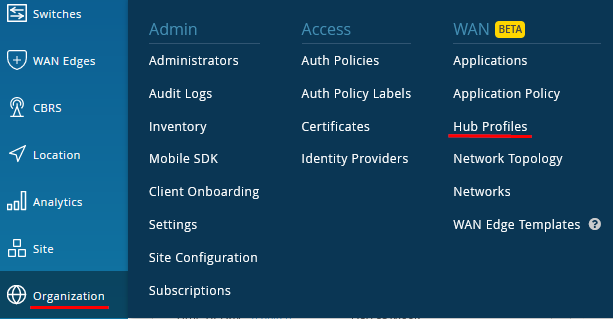
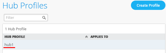
Go to Organization -> Hub Profiles
Note
You can avoid the work creating this Profile if you simply import the shared JSON.
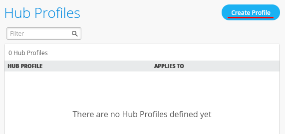
Click on “Create Profile”
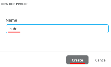
Example uses the name (although Site Location or standard naming conventions should be used) “hub1” then click on “Create”.
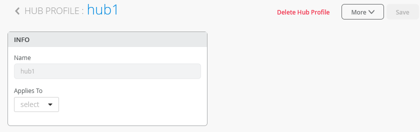
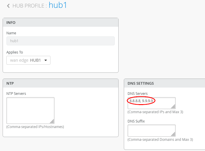
This will open the dialogue window to enter the configuration for the Hub
Configure the DNS Servers to use 8.8.8.8, 9.9.9.9 or DNS servers, which your company uses but must be reachable from the Hub device through the Underlay network.
Add the first WAN-Interface
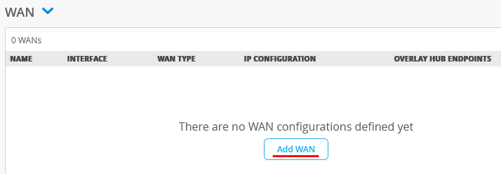
Configure a first WAN-Interface as follows
- Name=INET this indicates which Topology it’s going to use.
- The Overlay Hub Endpoint will be automatically generated and should be “hub1-INET”.
- Interface=ge-0/0/0
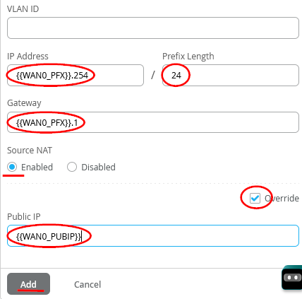
- IP Address={{WAN0_PFX}}.254 <—Please read Site Variables document if you are not familiar with variables
- Prefix Length=24
- Gateway={{WAN0_PFX}}.1
- Source NAT=Enabled <—We use NAT along with advertising the Public IP address below unless the WAN address is a publicly routable address
- Check Override for Public IP
- Public IP={{WAN0_PUBIP}}
Configure a second WAN-Interface as follows
- Name=MPLS this indicates which Topology it’s going to use. <—This is simply a label and not a technology
- The Overlay Hub Endpoint will be automatically generated and should be “hub1-MPLS”.
- As Interface=ge-0/0/1
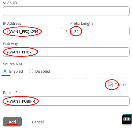
- IP Address={{WAN1_PFX}}.254
- Prefix Length=24
- Gateway={{WAN1_PFX}}.1
- Source NAT=Enabled
- Check Override for Public IP
- Public IP={{WAN1_PUBIP}}

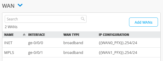
The end result overview should look like the below summary picture.
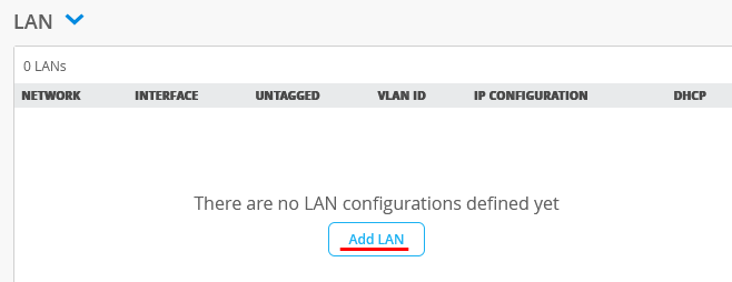
Add a LAN-Interface now
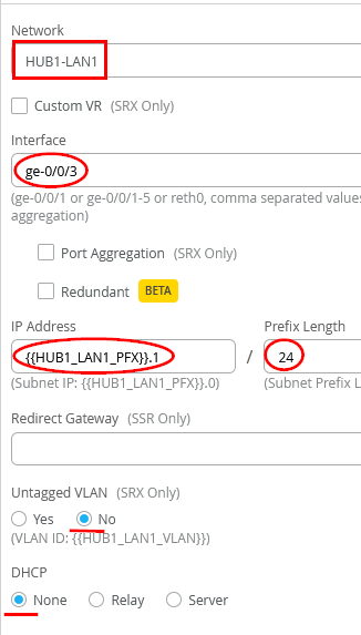
Configure the LAN-Interface as follows
- As Network select the existing=HUB1-LAN1
- As Interface=ge-0/0/3
- IP Address={{HUB1_LAN1_PFX}}.1
- DHCP=No (we don’t configure a local DHCP server yet even if we could)
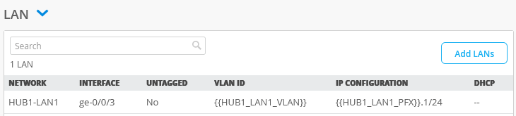
The end result overview should look like the below summary picture.
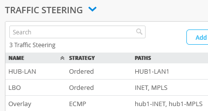
We always need to add Traffic Steering Policies, which describes how traffic is steered out the interfaces that were previously defined. These definitions explain traffic pattern for single interfaces or multiple interfaces and how you want your traffic to utilize these paths.
Overlay, WAN and LAN are defined as well as if you would like a specific order or Equal Cost Multi-Path (ECMP), so the combination of which interfaces and how those interfaces participate in the data flowing from the device, which the Hub Profile is applied to.
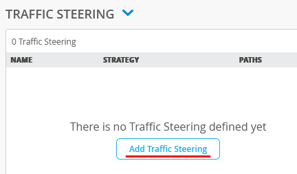
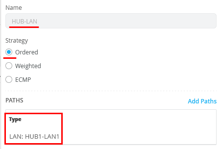
Configure the first Traffic Steering Policies as follows
- Name=HUB-LAN
- Strategy=Ordered
- As Path Type select LAN: HUB1-LAN1
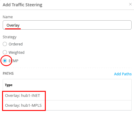
Configure the second Traffic Steering Policies as follows
- Name=Overlay
- Strategy=ECMP
- As Path Types we need to configure the two automatic Endpoints we’ve created automatically above based on our WAN-Interface configuration. So, select via “Add Paths” the Overlay Endpoints hub1-INET and hub1-MPLS please.
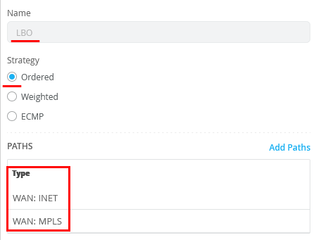
- Third we need to define WAN Interfaces to be used for Central Breakout (of internet traffic) on this Hub. Local Breakout is a term where the Spoke device will break out traffic to the Internet and Central Breakout is where the Internet bound traffic goes to the Hub device over the SD-WAN network, then breaks out. Here we are configuring Central Breakout so, configure:
- Name=LBO
- Strategy=Ordered
- As Path Type select WAN: INET and WAN: MPLS
The end result overview should look like the below summary picture.
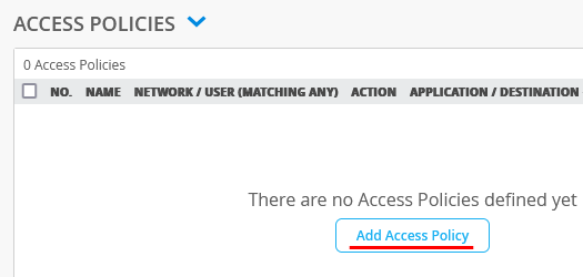
We now need to configure Access Policies to steer Traffic into Overlay, Local LAN and Central Breakout, which we defined in the Traffic Policies.
Warning
For 128T SSR’s the order of Rules does NOT matter when creating Access Policies! However, it is always good practice to move the more global rules to the bottom like one would do for a Firewall.
Note
There is no need to always define a Traffic Steering on each rule as must be done for a Juniper SRX. In the below you will see that some policies are only made with an access network and destination definition. This is because this system acts more like a Router. As in our case we announce all routes on each LAN-Interface independent if that is a Hub or Spoke the steering comes from the iBGP based route distribution, which the system does automatically when you build the Hub/Spoke VPN.
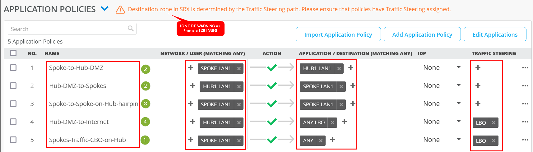
Implement the following list of Access Rules as a basic setup that allows all Traffic between Hub and Spokes, Spokes to Spokes (hairpin on the Hub) and then also using the Hub for central breakout towards the Internet for all Traffic not inside the VPN. Here is an explanation why we created those rules.
- First Rule (via as attached SPOKE-LAN1 networks) allows all other VPN Members in the Branch to initiate Traffic towards the local LAN-Interfaces of the Hub where usually an internal Server is attached in a DMZ.
- Second Rule is the opposite of the first allowing the Servers attached to the Lan-Interfaces at the Hub to initiate Traffic towards the Spokes (represented by SPOKE-LAN1 defined as 10.0.0.0/8) via Overlay using the VPN then.
- Third Rule number identifies Traffic from Spoke interfaces send to the Hub but the destination is an IP-Address (via SPOKE-LAN1 defined as 10.0.0.0/8) at another Spoke. So, this Traffic will be hair pinned at the Hub and forwarded back to the next Spoke via the Overlay VPN.
- Forth Rule allows Traffic that is initiated from IP-Addresses of the direct attached LAN interface of a Hub to use the WAN Underlay Interface (SNAT applied) to reach IP-Addresses in the Internet as local breakout. The ANY-LBO destination is defined as 0.0.0.0/0 so this will mean the remaining Internet. Be aware that one can NOT use the ANY destination here which has the same destination Target. It will be used for Overlay Traffic from the Spoke in the next Rule and the system would then not know that there are two traffic senders from different directions using the same breakout interface. The need is to have multiple definitions for 0.0.0.0/0 with different names in this case.
- The last Rule identifies all Traffic from the Spokes wanting to reach the remain IP-Address and not the HUB-LAN in the first rule. The ANY destination is defined as 0.0.0.0/0 so this will mean the remaining Internet. This Traffic will use the WAN Underlay Interface (SNAT applied) to reach IP-Addresses on the Internet as local breakout . This implements Central Break out at the Hub for all Spokes.
| no. | Rule Name | Network | Action | Destination | Steering |
| 1 | Spoke-to-Hub-DMZ | SPOKE-LAN1 | Pass | HUB1-LAN1 | N/A |
| 1 | Hub-DMZ-to-Spokes | HUB1-LAN1 | Pass | SPOKE-LAN1 | N/A |
| 3 | Spoke-to-Spoke-on-Hub-hairpin | SPOKE-LAN1 | Pass | SPOKE-LAN1 | N/A |
| 4 | Hub-DMZ-to-Internet | HUB1-LAN1 | Pass | ANY-LBO | LBO |
| 5 | Spokes-Traffic-CBO-on-Hub | SPOKE-LAN1 | Pass | ANY | LBO |
Note
The general Rule for SSR is to make Traffic flow between a Hub and Spoke the NAME of a Network used on one side has the be identical with the Name of the Network on the other Side. The Network Name for SSR is identical to a security tenant used for Traffic isolation hence they need to match on both sides.
The end result overview should look like the below summary picture.
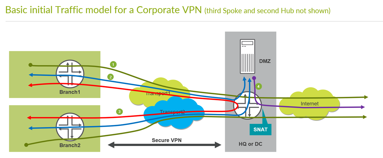
Remember the basic Traffic model we are implementing to see where the green counter marks match to which traffic direction. So please compare below and above pictures.
IMPORTANT to save your final changes in this Screen
Create second Hub as clone of the first Hub
Go to Organization -> Hub Profiles
Note
You can avoid the work creating this Profile if you simply import the shared JSON.
Create your second Profile based on the first one to save time. Click on the existing Hub1 Profile
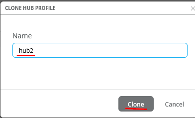
In the upper right corner of the screen press “More” -> “Clone”.

Name the new Hub “hub2” and press on “clone”-button.
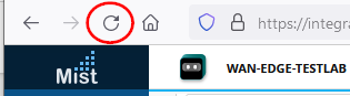
You might see a bug in the GUI where the new name does not match the new profile name like below.
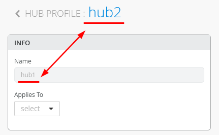
BEST PRACTICE: Always refresh your Browser after you cloned something. This will make sure all objects are REALLY refreshed!
Note
As we already made heavy use of site variables we do not need to edit the configuration of our WAN interfaces which limits the amount of changes on the clone to a minimum.
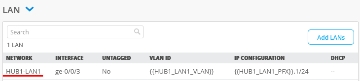
Click in the clone of the HUB1-LAN1 interface as we need to change that.
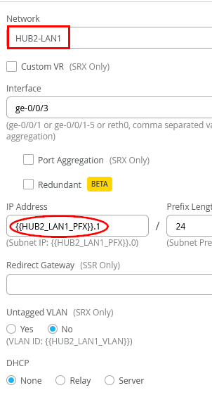
Change the Network to HUB2-LAN1 and the IP Address to {{HUB2_LAN1_PFX}}.1
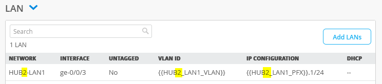
Check that the resulting LAN interface always states HUB2 and not HUB1 anymore.
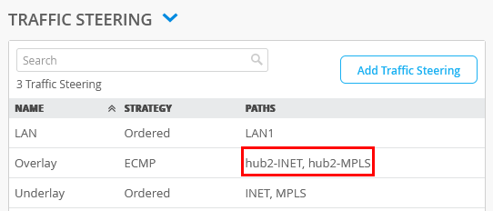
Please check that the Overlay Endpoints in the Overlay definition have really changed to hub2-INET and hub2-MPLS as they should.
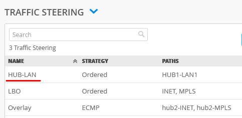
Next click under Traffic Steering on HUB-LAN as it still references the original hub
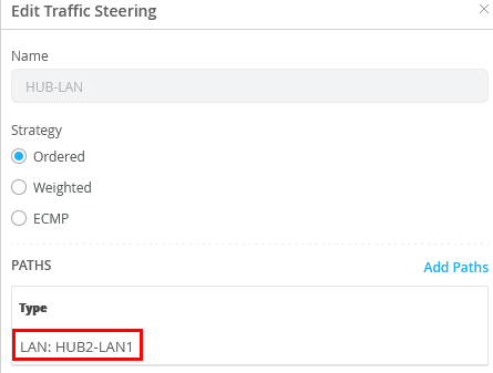
Edit the entry and change the path to LAN: HUB2-LAN1
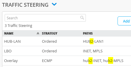
Check that all resulting Traffic Steering Paths now point to HUB2 and no longer to HUB1
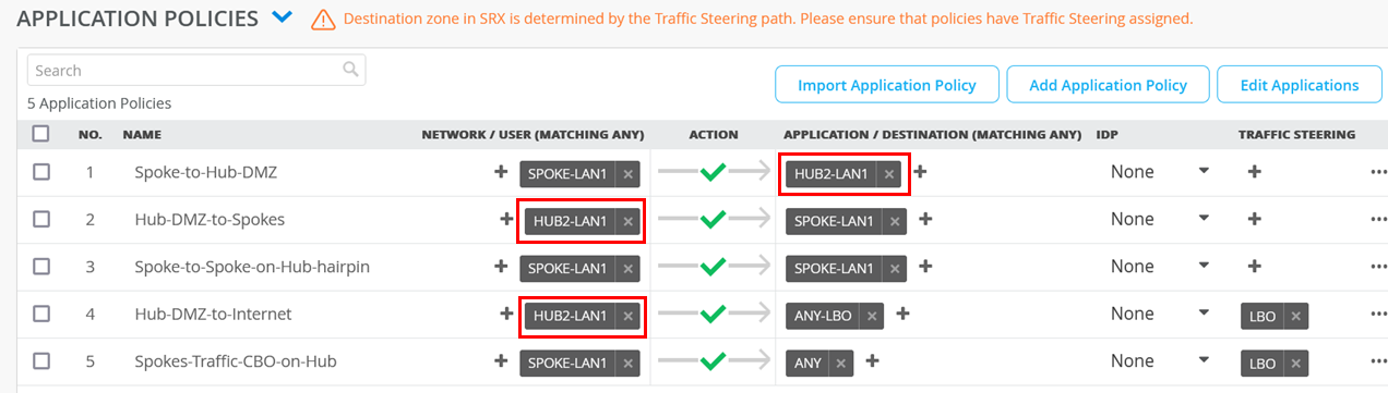
The only manual change we do need to make on our clone hub is the destination for the rules as indicated below.
| no. | Rule Name | Network | Action | Destination | Steering |
| 1 | Spoke-to-Hub-DMZ | SPOKE-LAN1 | Pass | HUB2-LAN1 | N/A |
| 1 | Hub-DMZ-to-Spokes | HUB2-LAN1 | Pass | SPOKE-LAN1 | N/A |
| 3 | Spoke-to-Spoke-on-Hub-hairpin | SPOKE-LAN1 | Pass | SPOKE-LAN1 | N/A |
| 4 | Hub-DMZ-to-Internet | HUB2-LAN1 | Pass | ANY-LBO | LBO |
| 5 | Spokes-Traffic-CBO-on-Hub | SPOKE-LAN1 | Pass | ANY | LBO |
So, change the destination of the second rule from HUB1-LAN to HUB2-LAN please.
IMPORTANT to save your final changes in this Screen