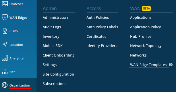
Go to Organization -> WAN Edge Templates.
Note
You can avoid the work creating this Template if you simply import the shared JSON discussed in other reference documentation. Remember you must do the Site assignments after this.
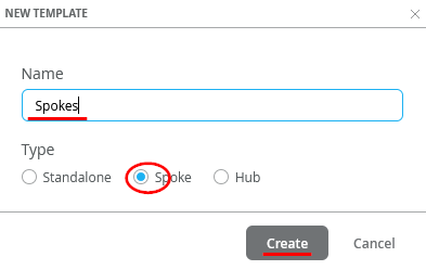
Create your entire Spoke Template via GUI. Click on “Create Template”

We create the Template for our Spokes. Naturally the name would be “Spokes” and the Type=Spoke to be used then click on “Create”.
There may be one Template or several Templates for your end sites (Spokes), with the goal to make them flexible enough to reduce the overall number of Templates required, which make standardization of your network much cleaner.
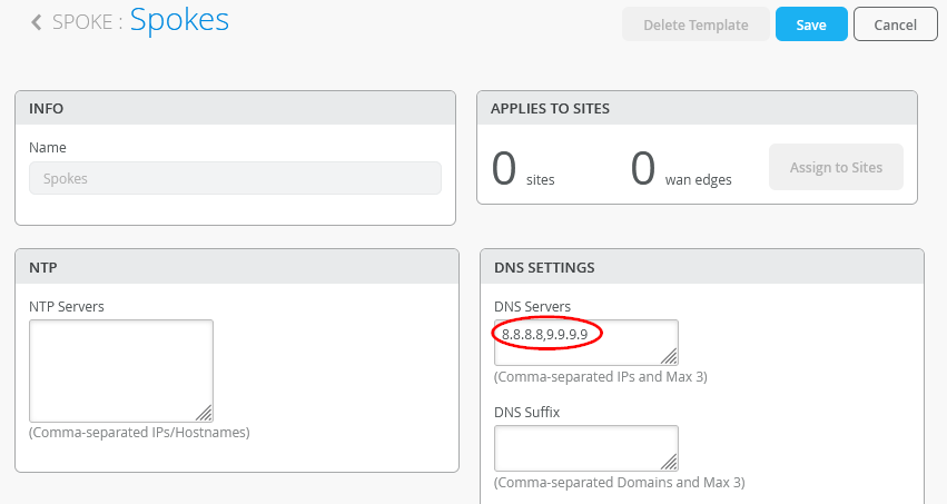
Configure the DNS Servers to use 8.8.8.8, 9.9.9.9 in our case.
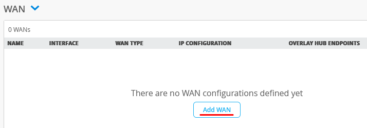
Add the first WAN-Interface
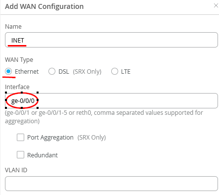
Configure the new WAN-Interface as follows
- Name=INET this indicates which Topology it’s going to use.
- As Interface=ge-0/0/0
- IP configuration=DHCP
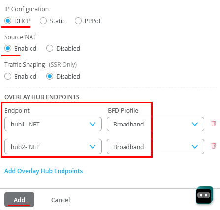
- Source NAT=Enabled
- Configure two VPN (on for each Hub) with Endpoint=hub1-INET and hub2-INET as Overlay Hub endpoints and used the BFD-Profile Broadband on both for now.
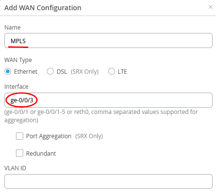
Configure a second WAN-Interface as follows
- Name=MPLS this indicates which Topology it’s going to use.
- As Interface=ge-0/0/3
- IP configuration=Static
- IP Address={{WAN1_PFX}}.2
- Prefix Length=24
- Gateway={{WAN1_PFX}}.1
- Source NAT=Enabled
- Configure two VPN (on for each Hub) with Endpoint=hub1-MPLS and hub2-MPLS as Overlay Hub endpoints and used the BFD-Profile Broadband on both for now.

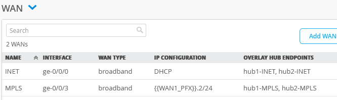
The end result overview should look like the below summary picture.
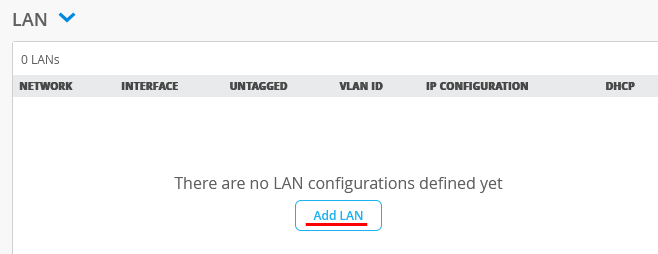
Add a LAN-Interface now
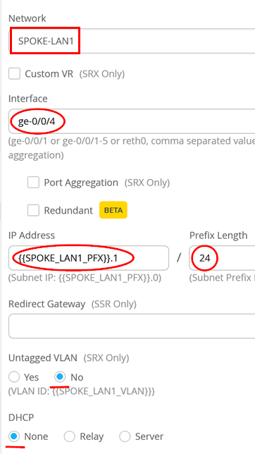
Configure the LAN-Interface as follows
- Select from the preconfigured list the Network=SPOKE-LAN1
- As Interface=ge-0/0/4
- IP Address={{SPOKE_LAN1_PFX}}.1
- Prefix Length=24
- Untagged VLAN=No (for our Lab it’s better to use tags even at the first vlan)
- DHCP=No (we don’t configure a local DHCP server yet even if we could)
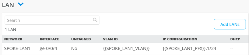
The end result overview should look like the below summary picture.
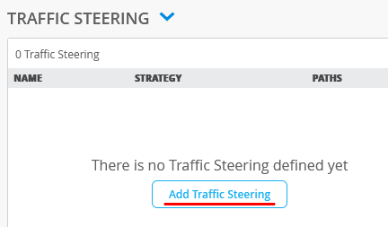
We always need to add Traffic Steering Policies.
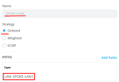
Configure the first Traffic Steering Policies as follows:
- Name=SPOKE-LANS
- Strategy=Ordered
- As Path Type select LAN: SPOKE-LAN1
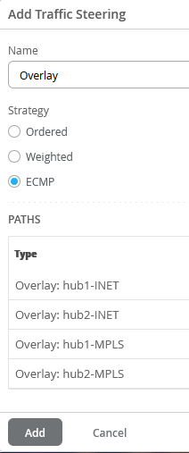
Configure the second Traffic Steering Policies as follows:
- Name=Overlay
- Strategy=ECMP
- As Path Types select all four Hub destination Hub Interfaces as there are Overlay: hub1-INET and Overlay: hub2-INET and Overlay: hub1-MPLS and finally Overlay: hub2-MPLS
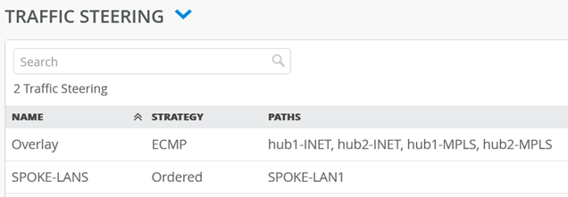
The end result overview should look like the below summary picture.
Note
Every Traffic Policy you have defined MUST be used at least once in an Access Policy!
We now need to configure Access Policies to steer Traffic into Overlay and Local.
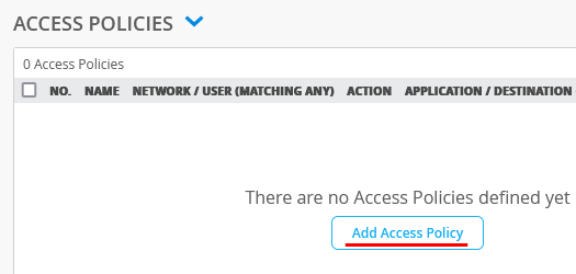
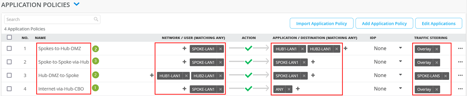
Implement the following list of Access Rules as a basic setup that allows all Traffic between Spoke and Spoke, Spokes and Hubs, Hubs to Spokes and if Traffic is not inside the VPN we send it default to the Hub for central breakout. Here is an explanation why we created those rules.
- First Rule allows Traffic that is initiated from IP-Addresses of the direct attached LAN interface when the Destination Prefix one the direct Address groups representing the LAN interface of our two Hubs.
- Second Rule allows Traffic that is initiated from IP-Addresses of the direct attached LAN interface to reach all IP-Addresses of other Spokes to be reached in the VPN using the Overlay. Remember SPOKE-LAN1 is 10.0.0.0/8 so everything. As its technically most of the times not possible (only expensive MPLS Networks with managed IP’s may give you a chance to do that) to send this Traffic directly to the other Spoke we will send it to the Hub and he will relay it for us.
- Third Rule allows Traffic that originally came (usually via Overlay) from a Hub to be forwarded to IP-Addresses of the direct attached LAN interface. So, something attached to the Hub like a Server in its DMZ is allowed to initiate Traffic towards the Branch devices at the Spoke.
- Fourth Rule is a catch-up Rule the allows ALL Traffic from LAN interface to forward to the Overlay (towards one of our Hubs). In our case the Hub applies SNAT to this Traffic and sends it to a WAN interface but this is defined in the Hub-Template. This Rule should typically be the LAST RULE of all your Access Rules and all above Rules should be more specific.
No. Rule Name Network Action Destination Steering
| no. | Rule Name | Network | Action | Destination | Stearing |
| 1 | Spoke-to-Hub-DMZ | SPOKE-LAN1 | Pass | HUB1-LAN1 + HUB2-LAN1 | Overlay |
| 1 | Spoke-to-Spoke-via-Hub | SPOKE-LAN1 | Pass | SPOKE-LAN1 | Overlay |
| 3 | Hub-DMZ-to-Spoke | HUB1-LAN1 + HUB2-LAN1 | Pass | SPOKE-LAN1 | SPOKE-LANS |
| 4 | Internet-via-Hub-CBO | SPOKE-LAN1 | Pass | ANY | Overlay |
Warning
The order of Rules does matter a lot when creating Access Policies for SRX! You must keep them in the order as they appear below! One can move them up/down at the right where the “…” sign is.
The end result overview should look like the below summary picture.
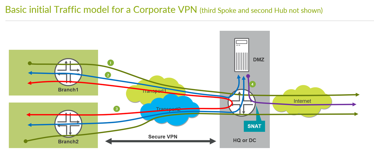
Remember the basic Traffic model we are implementing to see where the green counter marks match to which traffic direction. So please compare below and above pictures.
Note
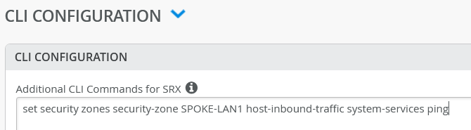
The default security configuration for SRX based devices does NOT allow ICMP-Ping from LAN attached device to the local Interface of the WAN-Edge Router. However, some devices are known to check this before they attempt to connect to the outside. Hence, it is recommended that you allow ICMP-Ping for debugging and device connectivity and override this default.
Add the following additional Junos CLI. It will allow you to Ping the local LAN-Interface for debugging.
set security zones security-zone SPOKE-LAN1 host-inbound-traffic system-services ping
This is how it will be seen in the GUI.
IMPORTANT to save your final changes!!

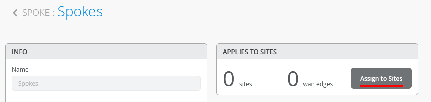
Assign Spoke Templates to Sites
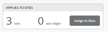
We go back to the Spoke Template and “Assign to Sites”.
Then select only the three “spokeX-site” and “Apply”.
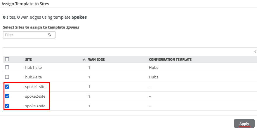
The result should indicate 3 Sites (the wan edges change when devices get assigned the these)