The AI Driven SD-WAN Secure Edge Connector (SEC) can provide connectivity to many SASE providers. This provides a simple augmentation of on-box IDS and URL filtering services. The SEC provides simplified workflows for Juniper SASE, Zscaler as well as additional providers though the custom option.
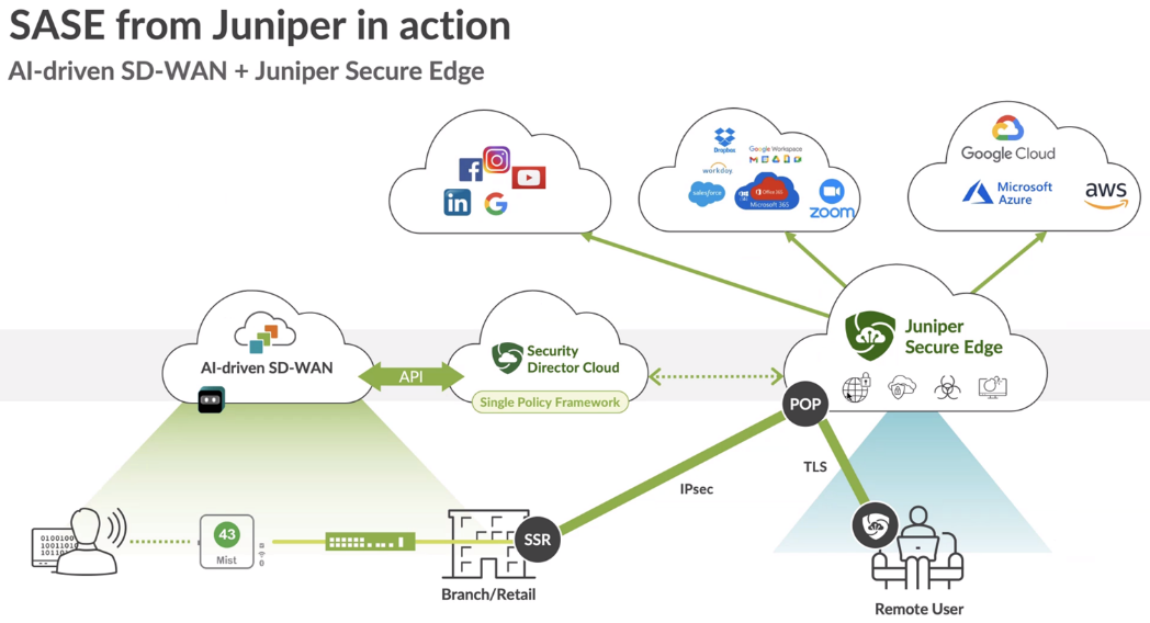

Juniper Secure Edge is an advanced Security Scanner located in the Cloud. With WAN-Edge devices one can decide which portion of the Traffic or all that is meant to be sent to the Internet must be inspected via Juniper Secure Edge before it is allowed to transit to the Internet. The Traffic can either originate from the LAN-Side of a Spoke or a Hub. The connection to the cloud is IPSec based in this case.
Create resources in SD-Cloud
We start with logging into SD-Cloud with a Web-Browser https://sdcloud.juniperclouds.net/ and your credentials.
Select the tenant (if you have multiple) at the upper right corner.
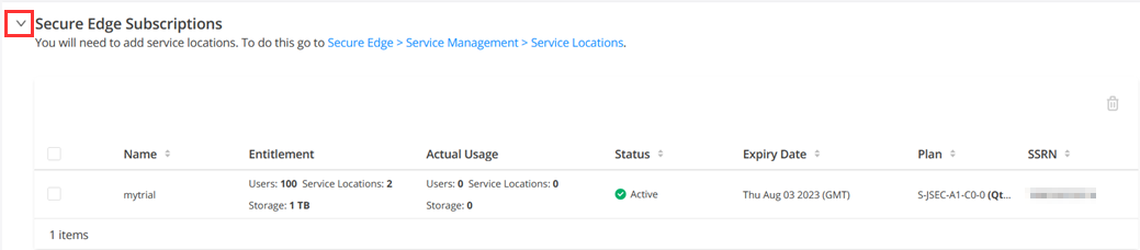
Check you Secure Edge Subscriptions
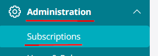
Under Administration -> Subscriptions:

Go to the Secure Edge Subscriptions section and make sure you have an active subscription.
Note
There is also an SRX Management Subscription Tab but that does not count even if a device is SRX based as the management in the case of WAN-Edge is not done via SD-Cloud.
Configure Service Locations
Service Location are vSRX based VPN-Gateways hosted in a Public Cloud for you. The Public IP-Address (unique per tenant and Service Location) is used to build the Tunnel between the branch and the SD-Cloud and to centrally breakout the Traffic when the destination is on the internet.
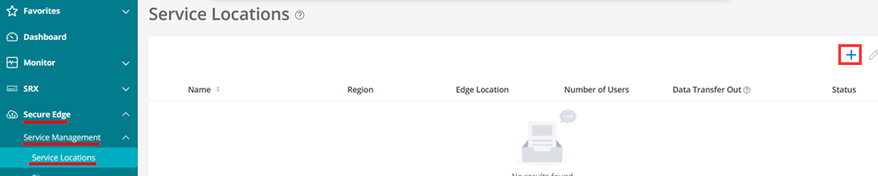
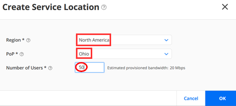
Go to Secure Edge >Service Management > Service Locations and click the plus (+) sign to create a new service location. Then fill out the following two example locations.
Our first Service Location will be configured as
- Region=North America
- PoP=Ohio
- Number of Users=50 (we split the exiting equally)
Our second Service Location will be configured as
- Region=North America
- PoP=Oregon
- Number of Users=50

This then starts the deployment of two vSRX instances as VPN-Gateways for our Tenant (they are not shared with other Tenants by design).
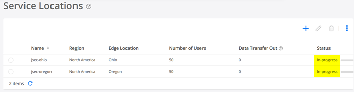
Warning
Wait for 10minutes before you continue!
When your Service Locations are available it should look like the below:
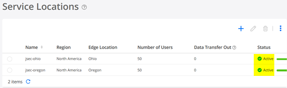
You should receive an Email, so check your Spam-Folder if it does not appear.

Configure Certificate Management
You must manage the device certificates to establish Transport Layer Security (TLS) or Secure Socket Layer (SSL) sessions. TLS or SSL uses public-private key technology that requires a paired private key and an authentication certificate. SSL encrypts communication between the web browser and webserver with a session key negotiated by the SSL server certificate.
Both on-premises users and roaming users require device certificates. You must install the SSL or TLS certificate in the end-users browser’s trusted root store. If this is not done, roaming users cannot use the service. For on-premises users, the SSL decrypt will break their connectivity. The certificate generation is a one-time activity and you must do it before deploying the security policies.
These certificates are used to decrypt the end user’s traffic, which will then be used by the Secure Edge policies.
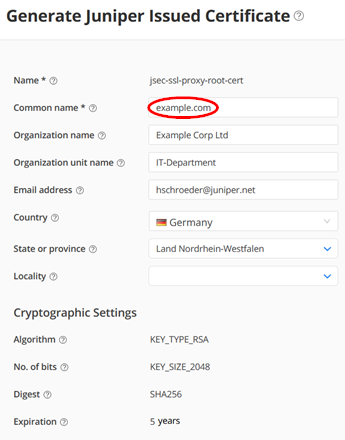
In our case we do not have a Corporate PKI so we leverage the offer to get signed certificates from Juniper as below:
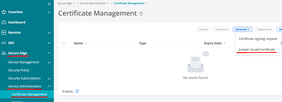
Fill in data but make sure the Common Name looks like an FQDN for an example corporate like example.com in our case.
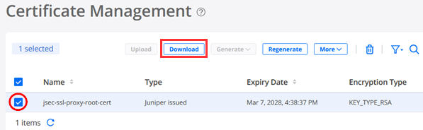
To be able use the SSL-Proxy ability later, download the generated certificate like below.
When you open the downloaded file, it should look like the below.
-----BEGIN CERTIFICATE-----
MIIG4jCCBMqgAwIBAgIIX3yPMZ7QT9MwDQYJKoZIhvcNAQEMBQAwgYgxCzAJBgNV
BAYTAlVTMQswCQYDVQQIEwJDQTESMBAGA1UEBxMJU3Vubnl2YWxlMR4wHAYDVQQK
.
.
JwePvBrmKGPph8k+8gL9Gqw+wnfaARP3fqp4TXUcp6twDMyP0OJR8tRm51keplVw
RAfTzy91Bhf261E62+MzKeh8J0Wi8q8Amaw6+aNVj8TcA9T/zotCI5JSkqV6+Wap
btLaf5DXSYliXWnDgt72sURF3bmUYjfDTmPgwzeMi/dal4IWUqk=
-----END CERTIFICATE-----
Note
LATER ON when using SSL-Proxy we need to make this certificate known to every Browser of every corporate client. HOW YOU ROLL THIS OUT is subject to individual Corporate Client management procedures and frameworks. This is usually a third-party product we cannot give guidance on in this document.
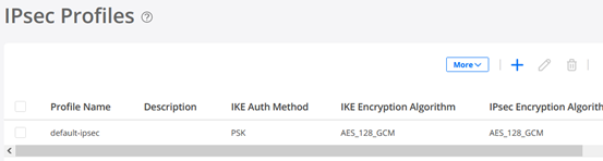
Create IPsec Profiles
It’s best practice to define the IPsec profile BEFORE you state this in the Site creation.
Go to Secure Edge >Service Management > Service Locations -> IPsec Profiles and click the plus (+) sign to create a new Profile.

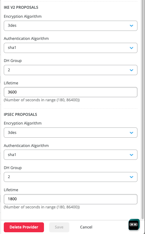
Use the Name=default-ipsec and KEEP ALL DEFAULTS for IKE and IPsec as they are currently not configurable on the Mist Cloud configuration side!
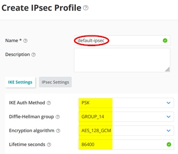
Again, do NOT change the defaults!
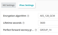
Your IPsec Profile should look like this.
Create a Site
Warning
Overlapping branch addresses are not supported to the same POP within Secure-Edge when using a stateful firewall at branch locations (e.g. SSR). This is since reverse path traffic to these overlapping IPs will be routed using ECMP across all connections rather than per session to the interface from which it was received. Consider it when you configure the Protected Networks for a Site.
Sites are typically SSR Branch devices using SD-Cloud Service Locations.
Go to Secure Edge >Service Management > Service Locations -> Sites and click the plus (+) sign to create a new Site.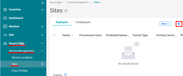
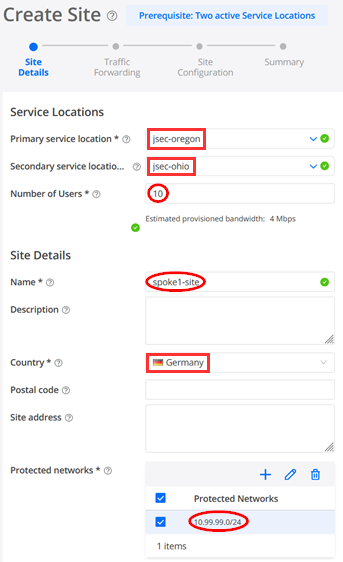
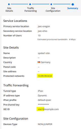
The configuration for the first Site is as follows with Site details first:
- Primary service location=jsec-oregon
- Secondary service location=jsec-oregon
- Number of Users=10
- Name=spoke1-site (we match the names in Mist Cloud to remember them better)
- Country=Germany (doesn’t matter really)
- Protected networks=10.99.99.0/24 (this is our LAN-Network)
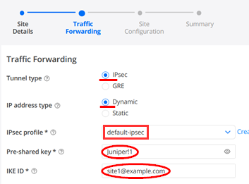
For Traffic Forwarding you configure:
- Tunnel type=IPsec
- IP address type=Dynamic
- IPsec profile=default-ipsec
- Pre-shared key=Juniper!1 (or something else you remember). Best practice is to define the PSK unique for each site in case a device gets compromised.
- IKE ID=site1@example.com (SHALL look like an Email Address and must be unique per Site)
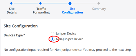
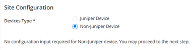
Under Site configuration you MUST use:
- Devices Type=Non-Juniper Device (This might look strange but Mist Managed devices do not have their configuration pushed via SD-Cloud hence this knob).
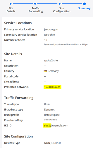
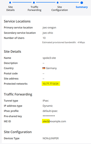
Review the Summary Page with a special view on protected Networks and the uniqueness of the IKE-ID.
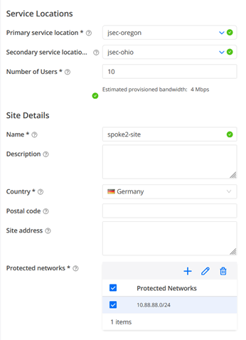
The configuration for the second Site is as follows with Site details first:
- Primary service location=jsec-oregon
- Secondary service location=jsec-oregon
- Number of Users=10
- Name=spoke2-site (we match the names in Mist Cloud to remember them better)
- Country=Germany (doesn’t matter really)
- Protected networks=10.88.88.0/24 (this is our LAN-Network)
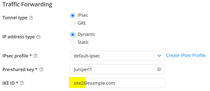
For Traffic Forwarding you configure:
- Tunnel type=IPsec
- IP address type=Dynamic
- IPsec profile=default-ipsec
- Pre-shared key=Juniper!1 (or something else you remember). Best practice is to define the PSK unique for each site in case a device gets compromised.
- IKE ID=site2@example.com (SHALL look like an Email Address and must be unique per Site)
Under Site configuration you MUST use:
- Devices Type=Non-Juniper Device (This might look strange but Mist Managed devices do not have their configuration pushed via SD-Cloud hence this knob).
Review the Summary Page with a special view on protected Networks and the uniqueness of the IKE-ID.
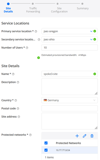
The configuration for the first Site is as follows with Site details first:
- Primary service location=jsec-oregon
- Secondary service location=jsec-oregon
- Number of Users=10
- Name=spoke3-site (we match the names in Mist Cloud to remember them better)
- Country=Germany (doesn’t matter really)
- Protected networks=10.77.77.0/24 (this is our LAN-Network)
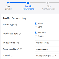
For Traffic Forwarding you configure:
- Tunnel type=IPsec
- IP address type=Dynamic
- IPsec profile=default-ipsec
- Pre-shared key=Juniper!1 (or something else you remember). Best practice is to define the PSK unique for each site in case a device gets compromised.
- IKE ID=site3@example.com (SHALL look like an Email Address and must be unique per Site)
Under Site configuration you MUST use:
- Devices Type=Non-Juniper Device (This might look strange but Mist Managed devices do not have their configuration pushed via SD-Cloud hence this knob).
Review the Summary Page with a special view on protected Networks and the uniqueness of the IKE-ID.
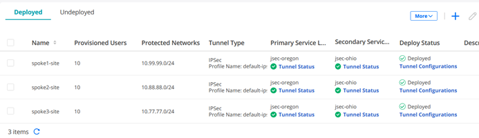
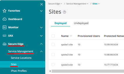
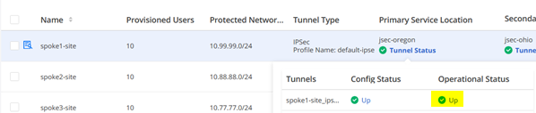
Your three configured Sites should now look like the below.
Deploy Secure Edge Policy
Warning
Even if you do not change the default Rule set you MUST execute “DEPLOY” to ensure that the Rules are loaded on your Service Locations!
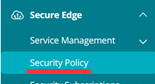
Go to Secure Edge -> Security Policy
We need to extend the default Security Policy set for better debugging. The default rule set does not allow ICMP to the outside (Internet) hence we cannot ping anything through the Cloud.
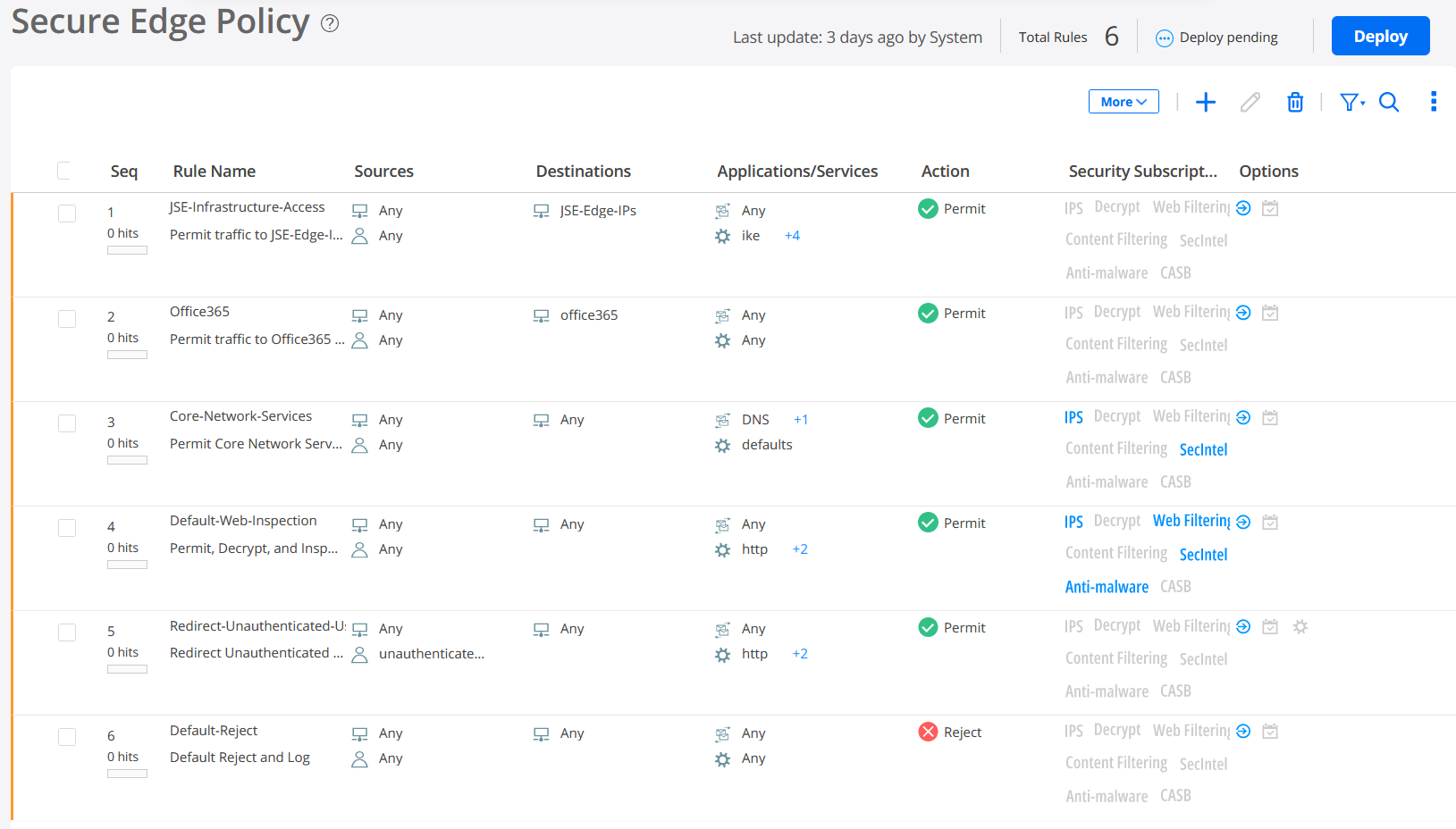
The default Security Policy ruleset is captured in the below.
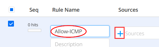
Using the (+) sign we start adding a new rule.

Give the new Rule the Rule name=Allow-ICMP and click on (+) to add Sources.
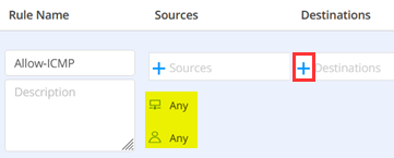
Under Sources leave the defaults to:
- Addresses=Any
- User Groups=Any

Having this implemented click on (+) to add Destinations.
Under Destinations leave the defaults to:
- Addresses=Any
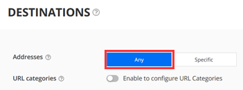
Having this implemented click on (+) to add Applications.
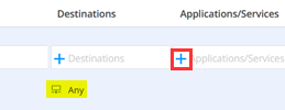
Under Applications/Services configure:
- Applications=Any
- Services=Specific
- (via search) Specific Service=icmp-all
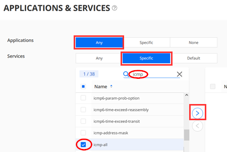
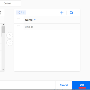
Make sure you transfer the Specific Service=icmp-all to the right Pane to activate it before you click “OK” in this dialogue.
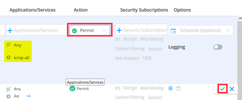
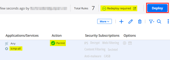
Now configure Action=Permit and submit your new Rule keeping the remaining defaults.
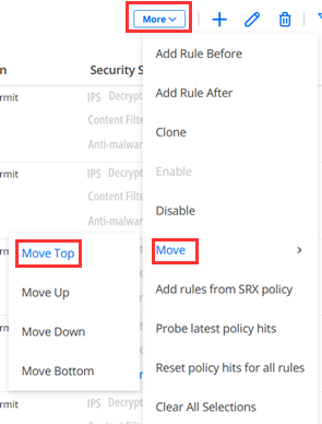
Your new Rule will usually become the last rule of the Ruleset. However, that is BELOW the global Rule that denies all further Traffic. Hence it will never be used as the Rule above already stops all further Traffic. We decided to put this Rule at the Top to activate it. So, select that Rule as below
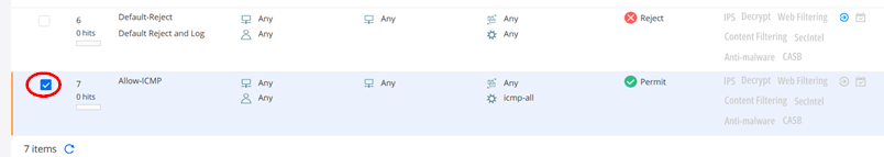
Then using Move -> Move -> Move Top we position this Rule at the Top of our entire Rules-set.
Whenever you change a Rule set you must hit the “Deploy” Button else you have not completed the Task and the Ruleset on the Service Location is still the old, not updated, Rule set.
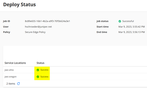
Check Run now and then “OK”

After a minute (or two) the Service Location should have the updated rule set.
MANDATORY: Check that all Rules are applied now.

Get Tunnel configuration parameters to apply on Mist side
In SD-Cloud the last remaining Step is to collect the created Data for each Site to then be able to complete the configuration in Mist to make the connection to SD-Cloud.
Note
Today there is no automated config push to sync the two clouds (its on the Roadmap) hence you need to do this manually.
Go back to Secure Edge >Service Management > Service Locations -> Sites
For each Spoke site click on “Tunnel Configuration” and then check the “MIST Managed Device” Tab for information. You can copy from there the minimum information you need to extract is:
- Pre Shared Key
- Local ID
- For each Service Location Tunnel
- IP
- Remote ID
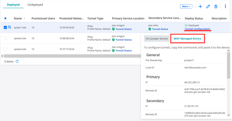
Here is an example of the extracted information for Site1
General spoke1-site

Pre Shared Key Juniper!1
Local ID site1@example.com

Primary
IP 44.225.209.13
Remote ID 4c011f96-ece7-4e78-8c19-8ddd14402ecb.jsec-gen.juniper.net

Secondary
IP 3.130.70.175
Remote ID 13df5633-e8cd-4c54-aae4-5d52d5cd6272.jsec-gen.juniper.net

IKE Proposals
Authentication Method pre-shared-keys
DH group group14
Encryption algorithm aes-128-gcm
Lifetime 86400

IPsec Proposals
Protocol esp
Encryption algorithm aes-128-gcm
Lifetime 3600
PFS Group group14
Here is an example of the extracted information for Site2
General spoke2-site

Pre Shared Key Juniper!1
Local ID site2@example.com

Primary
IP 3.130.70.175
Remote ID 13df5633-e8cd-4c54-aae4-5d52d5cd6272.jsec-gen.juniper.net

Secondary
IP 44.225.209.13
Remote ID 4c011f96-ece7-4e78-8c19-8ddd14402ecb.jsec-gen.juniper.net

IKE Proposals
Authentication Method pre-shared-keys
DH group group14
Encryption algorithm aes-128-gcm
Lifetime 86400

IPsec Proposals
Protocol esp
Encryption algorithm aes-128-gcm
Lifetime 3600
PFS Group group14
Here is an example of the extracted information for Site3
General spoke3-site
Pre Shared Key Juniper!1
Local ID site3@example.com
Primary
IP 44.225.209.13
Remote ID 4c011f96-ece7-4e78-8c19-8ddd14402ecb.jsec-gen.juniper.net
Secondary
IP 3.130.70.175
Remote ID 13df5633-e8cd-4c54-aae4-5d52d5cd6272.jsec-gen.juniper.net
IKE Proposals
Authentication Method pre-shared-keys
DH group group14
Encryption algorithm aes-128-gcm
Lifetime 86400
IPsec Proposals
Protocol esp
Encryption algorithm aes-128-gcm
Lifetime 3600
PFS Group group14
Create Secure Edge Tunnels in Mist WAN-Edge
Configure the other side to build these Tunnels.
Note
We assume here that you have SSR as branch device deployed. If you have not done it yet, do it now and then come back.
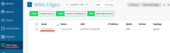
In Mist Cloud GUI go to WAN-Edges and pick a Site with a deployed Branch device like below shown.
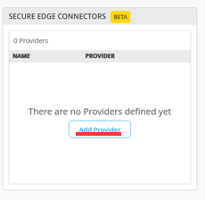
Under Secure Edge Connectors -> Add Provider.
Note
Leave all probe IP’s EMPTY! IPsec Tunnels do not need extra monitoring such as GRE would require.
Warning
Do NOT enable ICMP “Probe IPs” in an SSR-based Secure-Edge configuration. These ICMP probes will be sourced from a non-routable IP toward the Secure-Edge and dropped due to policy. Note also that this source address will also be overlapping at all branches, so routing to more than one branch with a Probe IP address is not currently supported.
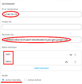
Configure the following for the first Site we add:
- Name=site1-to-sdcloud
- Provider=Juniper Secure Edge
- Local ID=site1@example.com
- Pre-Shared Key=Juniper!1
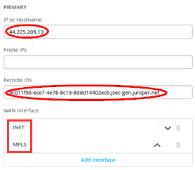
- Primary
- IP or Hostname=<IP-Address> from SD-Cloud Tunnel configuration
- Probe IP’s=Leave EMPTY!
- Remote ID=<UUID>.jsec-gen.juniper.net from SD-Cloud Tunnel configuration
- WAN Interface
- WAN0=INET
- WAN1=MPLS
- Secondary
- IP or Hostname=<IP-Address> from SD-Cloud Tunnel configuration
- Probe IP’s=Leave EMPTY!
- Remote ID=<UUID>.jsec-gen.juniper.net from SD-Cloud Tunnel configuration
- WAN Interface
- WAN0=INET
- WAN1=MPLS
- Mode=Active-Standby
Graphical user interface, text, application, email Description automatically generated
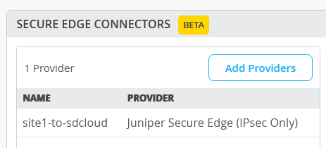
You should now see the added Secure Edge Connector.
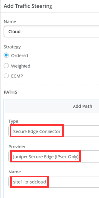
We are not finished yet. Next, we need to add a new Traffic Steering Path on the WAN Edge Template or device like the below one where we configure:
- Name=Cloud
- Strategy=Ordered
- Paths
- Type=Secure Edge Connector
- Provider=Juniper Secure Edge
- Name=site1-to-sdcloud
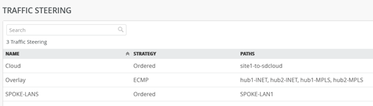
Updated Traffic Steering should look like now.
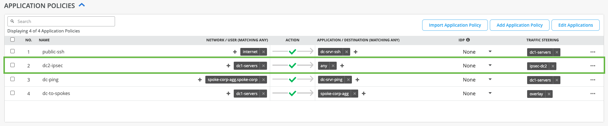
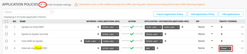
To quickly test our design, we modify the local Application Policies on that device only. In our case we leave all Traffic between Spoke <-> Hubs and Spokes <-> Spoke in the VPN but all Traffic from Spokes to Internet no longer is sent to the Hub for Central Breakout. Instead, we send this Traffic towards SD-Cloud now.
For SSR Devices the change is done (like the other) in the following Way:
- Check Override Template Settings
- Change the last Rule:
- Name=Internet-via-Cloud-CBO
- Traffic Steering=Cloud
Once you “Save” this new configuration the Tunnel(s) towards SD-Cloud will be typically built in 2-3 Minutes.
OPTIONAL: Depending on your environment you may be able to see the communication of the IPsec Tunnel towards SD-Cloud as in this example”
root@aidelab-dc51-srv:~# tcpdump -eni fabric6 port 4500
tcpdump: verbose output suppressed, use -v or -vv for full protocol decode
listening on fabric6, link-type EN10MB (Ethernet), capture size 262144 bytes
18:43:46.835469 52:54:00:f4:02:77 > 52:54:00:14:07:6c, ethertype IPv4 (0x0800), length 317: 192.168.173.191.16534 > 44.225.209.13.4500: NONESP-encap: isakmp: child_sa ikev2_auth[I]
18:43:46.879282 52:54:00:f4:02:77 > 52:54:00:14:07:6c, ethertype IPv4 (0x0800), length 317: 192.168.173.191.16535 > 3.130.70.175.4500: NONESP-encap: isakmp: child_sa ikev2_auth[I]
18:43:46.884834 52:54:00:14:07:6c > 52:54:00:f4:02:77, ethertype IPv4 (0x0800), length 292: 44.225.209.13.4500 > 192.168.173.191.16534: NONESP-encap: isakmp: child_sa ikev2_auth[R]
18:43:46.974426 52:54:00:14:07:6c > 52:54:00:f4:02:77, ethertype IPv4 (0x0800), length 292: 3.130.70.175.4500 > 192.168.173.191.16535: NONESP-encap: isakmp: child_sa ikev2_auth[R]
18:43:58.001576 52:54:00:14:07:6c > 52:54:00:f4:02:77, ethertype IPv4 (0x0800), length 103: 44.225.209.13.4500 > 192.168.173.191.16534: NONESP-encap: isakmp: parent_sa inf2
18:43:58.002603 52:54:00:f4:02:77 > 52:54:00:14:07:6c, ethertype IPv4 (0x0800), length 103: 192.168.173.191.16534 > 44.225.209.13.4500: NONESP-encap: isakmp: parent_sa inf2[IR]
18:44:06.111512 52:54:00:14:07:6c > 52:54:00:f4:02:77, ethertype IPv4 (0x0800), length 103: 3.130.70.175.4500 > 192.168.173.191.16535: NONESP-encap: isakmp: parent_sa inf2
18:44:06.112368 52:54:00:f4:02:77 > 52:54:00:14:07:6c, ethertype IPv4 (0x0800), length 103: 192.168.173.191.16535 > 3.130.70.175.4500: NONESP-encap: isakmp: parent_sa inf2[IR]
18:44:06.896312 52:54:00:f4:02:77 > 52:54:00:14:07:6c, ethertype IPv4 (0x0800), length 103: 192.168.173.191.16534 > 44.225.209.13.4500: NONESP-encap: isakmp: child_sa inf2[I]
18:44:06.922069 52:54:00:14:07:6c > 52:54:00:f4:02:77, ethertype IPv4 (0x0800), length 103: 44.225.209.13.4500 > 192.168.173.191.16534: NONESP-encap: isakmp: child_sa inf2[R]
18:44:07.022463 52:54:00:f4:02:77 > 52:54:00:14:07:6c, ethertype IPv4 (0x0800), length 103: 192.168.173.191.16535 > 3.130.70.175.4500: NONESP-encap: isakmp: child_sa inf2[I]
18:44:07.022502 52:54:00:14:07:6c > 52:54:00:f4:02:77, ethertype IPv4 (0x0800), length 43: 44.225.209.13.4500 > 192.168.173.191.16534: isakmp-nat-keep-alive
18:44:07.097695 52:54:00:14:07:6c > 52:54:00:f4:02:77, ethertype IPv4 (0x0800), length 103: 3.130.70.175.4500 > 192.168.173.191.16535: NONESP-encap: isakmp: child_sa inf2[R]
18:44:07.113678 52:54:00:14:07:6c > 52:54:00:f4:02:77, ethertype IPv4 (0x0800), length 43: 3.130.70.175.4500 > 192.168.173.191.16535: isakmp-nat-keep-alive
After the Tunnels are established, you will find information about those in WAN Insights of the device.
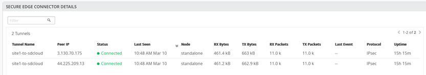
You can also check if your Tunnels are established in SD-Cloud looking at the Dashboard and in the Service Location itself like below indicated.
Now use a desktop VM attached to the device (in our case desktop1 VM) to check the new Traffic flow. Ping something on the Internet. It should not be a surprise if the latency is now a bit longer, depending on the distance to AWS where the Service Location is.
Keep in mind that this ping won’t work if you forgot to apply the icmp-Rule above in the Secure Edge -> Security Policy

root@desktop1:~# ping 8.8.8.8
PING 8.8.8.8 (8.8.8.8) 56(84) bytes of data.
64 bytes from 8.8.8.8: icmp_seq=1 ttl=100 time=40.5 ms
64 bytes from 8.8.8.8: icmp_seq=2 ttl=100 time=39.2 ms
64 bytes from 8.8.8.8: icmp_seq=3 ttl=100 time=38.0 ms
64 bytes from 8.8.8.8: icmp_seq=4 ttl=100 time=37.9 ms
^C
--- 8.8.8.8 ping statistics ---
4 packets transmitted, 4 received, 0% packet loss, time 3004ms
rtt min/avg/max/mdev = 37.942/38.914/40.507/1.059 ms

root@desktop1:~# ping 9.9.9.9
PING 9.9.9.9 (9.9.9.9) 56(84) bytes of data.
64 bytes from 9.9.9.9: icmp_seq=1 ttl=41 time=35.8 ms
64 bytes from 9.9.9.9: icmp_seq=2 ttl=41 time=34.3 ms
64 bytes from 9.9.9.9: icmp_seq=3 ttl=41 time=34.9 ms
64 bytes from 9.9.9.9: icmp_seq=4 ttl=41 time=33.7 ms
^C
--- 9.9.9.9 ping statistics ---
4 packets transmitted, 4 received, 0% packet loss, time 3001ms
rtt min/avg/max/mdev = 33.722/34.686/35.824/0.782 ms
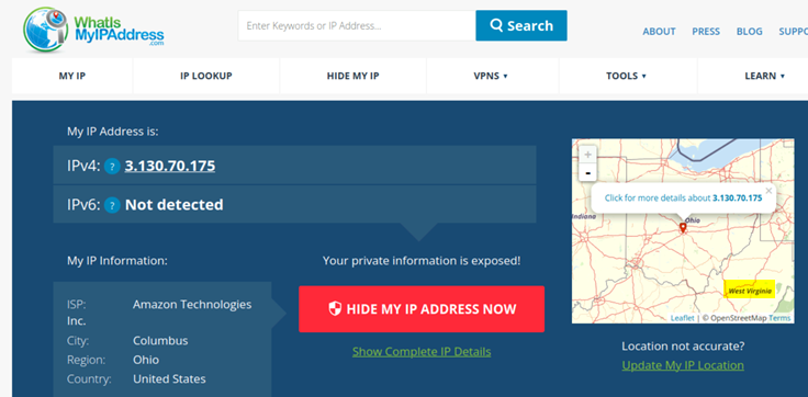
The next check is to open a Browser inside the desktop VM and use a site like https://whatismyipaddress.com/ to analyze your Source-IP Address towards the Internet. With our Tunnel towards the Service Location in SD-Cloud you should only see one of the two IP-Addresses o the service locations as the Public Address is shared between IPsec Tunnel termination and Traffic from Branch Devices via SD-Cloud towards Internet.
In the screenshot below Traffic is leaving though the Primary Service Location
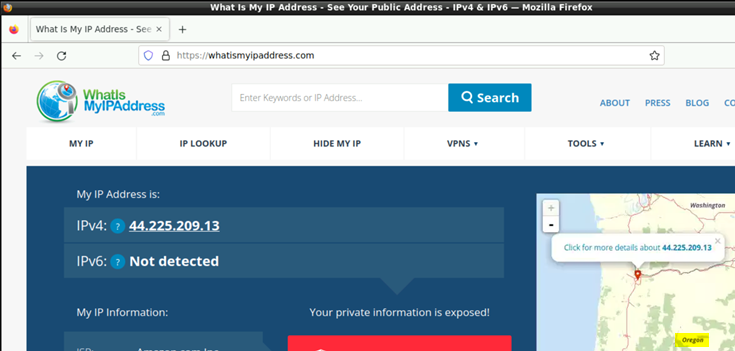
In the screenshot below Traffic is leaving though the Secondary Service Location
Note
The configuration of site2 and site3 is not shown here! It’s just a repeat of this section with the changed values extracted from SD-Cloud.
ZSCALER
WAN Assurance provdes a simplified workflow for Zscaler default connectivity. The Add Provider -> Zscaler workflow gives users a simple way to build connections from their devices using known defaults. If additional values need to be specified, please use Provider -> Custom
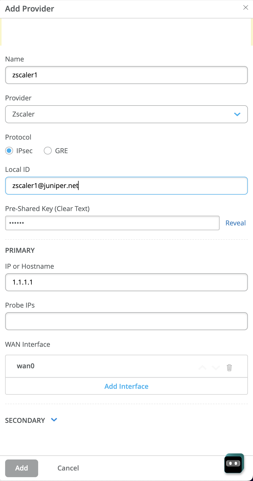
Example of Zscaler SEC provider bound to WAN0. A secondary tunnel can be created.
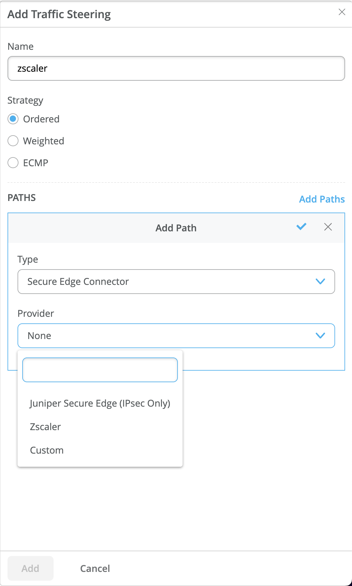
Add Traffic Steering and Application Policy for path and application policy creation.

CUSTOM
The Add Provider -> Custom workflow gives users the ability to select to add one or multiple SEC providers.
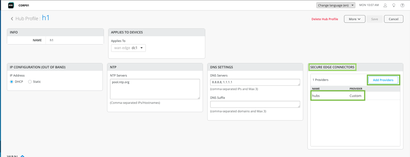
Example of custom SEC provider bound to WAN0.
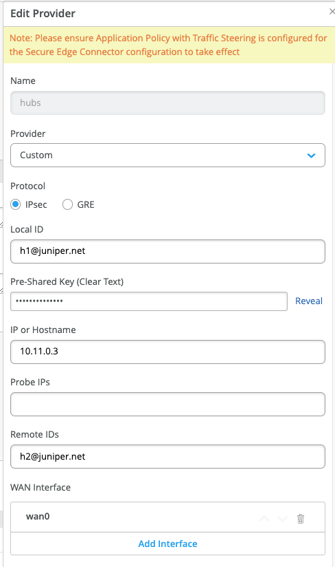
Add Traffic Steering and Application Policy for path and application policy creation.