Here we describe an example of an implementation of SD-WAN with a typical Hub and Spoke scenario leveraging different transport technologies to show how it is implemented. Assume one builds a Lab to test this out before the actual roll-out happens. This is what you see then below.
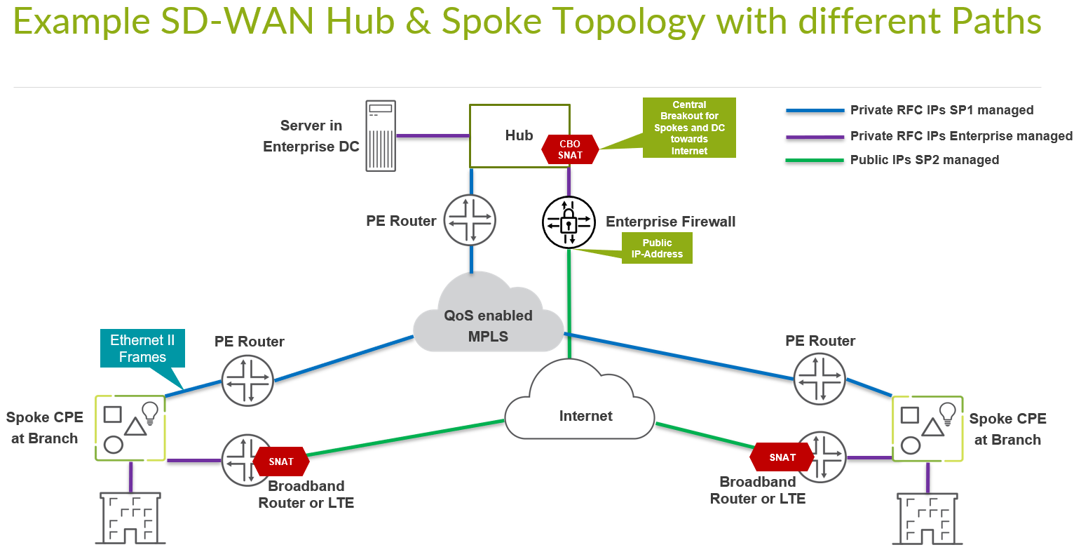
A Lab (simulating the real world) would have two Underlay Paths with different behavior.
- Emulating an MPLS path (without the MPLS framing in-between) with Private IP’s that are visible end to end. In a real-world environment those private IP-Addresses are managed distributed by the Router-Reflector of the Service Provider of the MPLS-Network. Hub’s and Spokes will get static IP’s assigned to the interfaces.
- An Internet path that is heavily subjected by all kinds of NAT that may make the connection of devices difficult. Still, it’s what you will see in real live environments today outside of the Lab.
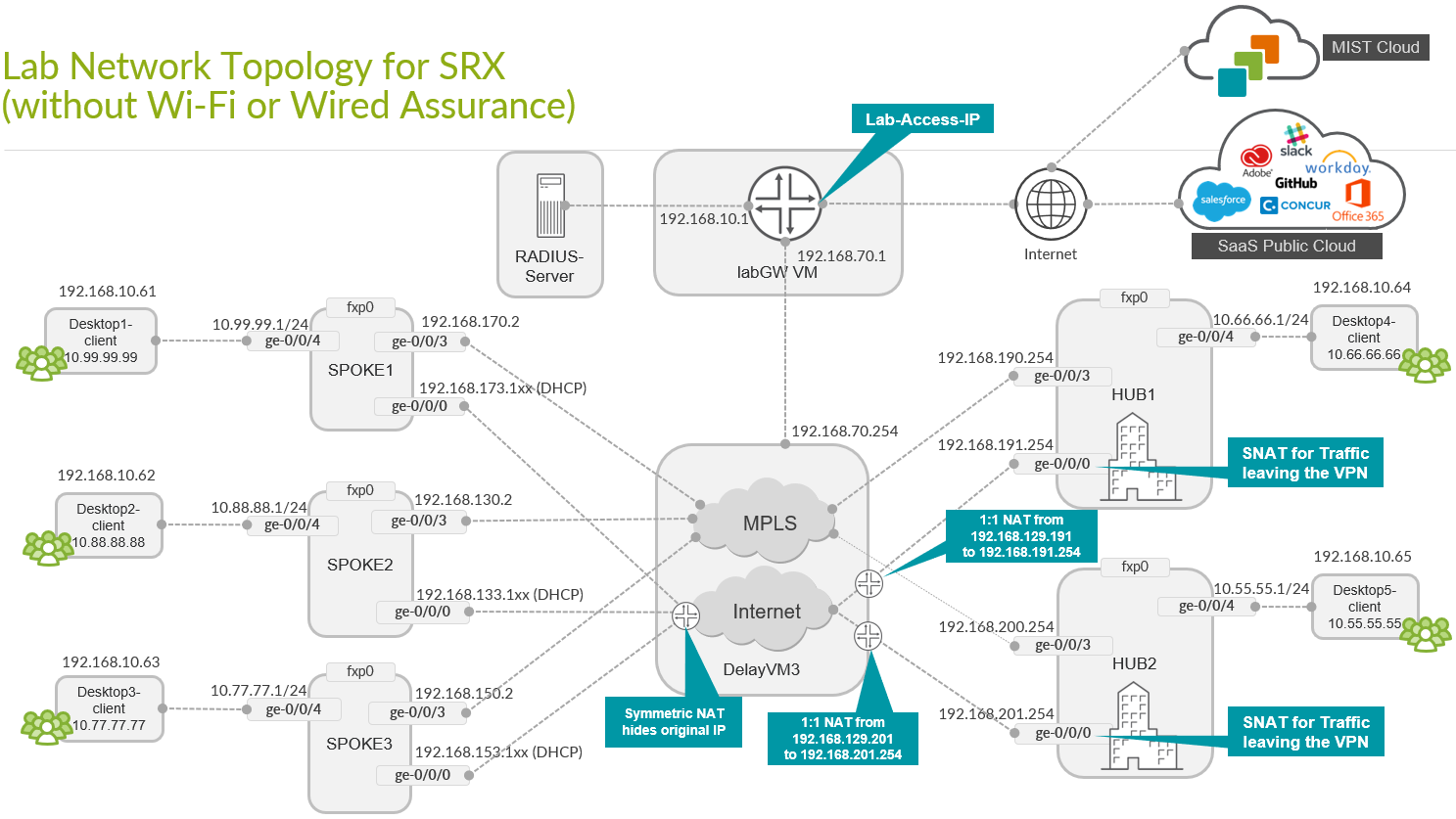
- Spoke devices will get a DHCP-Lease from an emulated local Broadband Router. The emulated Router will apply Symmetrical Source NAT as usual these days (especially if the device is connected via DS-Lite). This will force the Spoke to open a Tunnel towards a Public IP of the Hub via means of IKE (UDP destination port:500) and IPsec NAT-T (UDP destination port:4500).
- Hub device will get a private static IP address assigned to the local Interface. In front of the Hub there will be an emulated Public IP where all Spokes must send the Traffic to if they want to connect to the Hub of our Internet. We then emulate a Router or Firewall which applies 1:1 NAT forwarding to the private Interface IP Address of the Hub. This emulates the exact behavior one would see when the Hub is a VM inside a Public Cloud. A Public Cloud would not give you the ability of assigning a Public IP straight to an Interface of your Hub VM.
- An LTE-Moden connection of a Spoke is expected to have the same topology requirements. Typically the Mobile Service Provider does some kind of CG-NAT in his network.
- Both Paths are assumed to be completely isolated from each other (via internal Firewall). Any cross-talk would have to leverage the Hub which has Interfaces into both paths for fail-over.
A valid APP Track license is MANDATORY for all SD-WAN SRX based devices! Make sure you have those licenses installed to be able to use them as Hub or Spoke for WAN-Edge.
One can check if you have a valid License installed in the following way.
# if your device is a vSRX or SRX1500
# then check if your appid-licence is still valid and that you have one
show system license | match appid-sig
appid-sig 0 1 0 2022-09-21 00:00:00 UTC
.
.

# if your device is an SRX3xx
# then check if your idp-licence is still valid and that you have one
show system license | match idp-sig
idp-sig 0 5 0 2022-09-22 00:00:00 UTC
.
.
Create a basic SD-WAN Topology with 3 Spokes and 2 Hubs
Our Lab will have the default structure where we try to emulate the following:
- Installation of 3 Spoke Devices
- Installation of 2 Hub Devices
- Two Underlay Paths with different behavior. In the Lab the Underlay Address range utilized here is 192.168.0.0/16
- Emulated MPLS Path with private IP-Addresses.
- Emulated Internet Path, subjected to NAT.
- An Overlay Network managed by Enterprise on their own. It’s assigned on the LAN side of Hubs and Spokes. In the Lab the Overlay Address range utilized here is 10.0.0.0/8
The following is implemented in this example.
| Device | Interface | IF-Type | Path | IP-Address | Assigned |
| Spoke1 | ge-0/0/0 | WAN | INET | 192.168.173.1xx | DHCP |
| Spoke1 | ge-0/0/3 | WAN | MPLS | 192.168.170.2 | static |
| Spoke1 | ge-0/0/4 | LAN | Overlay | 10.99.99.1/24 | static |
| Spoke2 | ge-0/0/0 | WAN | INET | 192.168.133.1xx | DHCP |
| Spoke2 | ge-0/0/3 | WAN | MPLS | 192.168.130.2 | static |
| Spoke2 | ge-0/0/4 | LAN | Overlay | 10.88.88.1/24 | static |
| Spoke3 | ge-0/0/0 | WAN | INET | 192.168.153.1xx | DHCP |
| Spoke3 | ge-0/0/3 | WAN | MPLS | 192.168.150.2 | static |
| Spoke3 | ge-0/0/4 | LAN | Overlay | 10.77.77.1/24 | static |
| Hub1 | ge-0/0/0 | WAN | INET | 92.168.191.254 | static |
| Hub1 | ge-0/0/3 | WAN | MPLS | 192.168.190.254 | static |
| Hub1 | ge-0/0/4 | LAN | Overlay | 10.66.66.1/24 | static |
| Hub2 | ge-0/0/0 | WAN | INET | 192.168.201.254 | static |
| Hub2 | ge-0/0/3 | WAN | MPLS | 192.168.200.254 | static |
| Hub2 | ge-0/0/4 | LAN | OVERLAY | 10.55.55.1/24 | static |
In this Lab the emulated Public IPs are 192.168.129.191 for Hub1 and 192.168.129.201 for Hub2 that the Spokes are required to connect to.
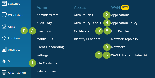
The workflow one should use when creating a WAN Edge SD-WAN design is:
- Create a Site for each device. We recommend to assign Site-specific Variables to limit the number of individual setups for each device. On should spend some time to check how to use templates instead. Also set Root-Passwords for WAN-Edge (and Switches). For SRX based device make sure that the Device has an APP-Track license and it’s marked as supported for the Site.
- Create Applications. Here the mean that you define only destination IP-Prefixes which are used to define where Traffic has to go to in the VPN. Do not use any other metric above Layer-3 information like Ports and others. We do that later.
- Create Networks. Those are used to define the source of Traffic via IP-Prefixes so it’s kind of the other side of what we define in the applications. Networks can also contain Overlay information which is why the logical order is in this way made.
- OPTIONAL: We may create Application Policy’s. This is suggested for larger organizations but not required in our simple design.
- Create a Hub Profile for the first Hub.
- Clone the Hub Profile for the first Hub to create the second Hub. Modify the candidate configuration for the second Hub accordingly and save the result.
- Create Template for our Spokes. We create a single Template for all three Spokes and the individual changes are done via variables.
- You then assign the Spoke Templates to the Sites.
- You launch your Devices via Claim or Adopt-Method so that they get visible in the Inventory of your Organization.
- Inside the Inventory assign the Devices to each Site.
- For the two Hubs you need to assign then the two devices in the Hub-Sites to the Hub Profiles.
- For each site check that Mist cloud has captured the host-name from the device. If needed add some additional CLI commands. Activate the configuration management of the Device.

The below is the order of what we are going to touch in the Workflow in the GUI