Create a Topology with High-Avail Hub and Spoke 128T SSR Routers
The following rules apply to SSR device based HA-Cluster configurations:
Note – Devices in an HA pair must be identical. An HA pair with two SSR120s will work. An HA pair with one SSR120 and one SSR120-AE will not work.
- The Interface names will follow the following pattern when you define them for each node:
- Node0=ge-0/0/x
- Node1=ge-1/0/x
- WAN Interfaces for HA-Hubs MUST have static IP-Addresses. So, you will define a WAN interface per each Path and Node. This will cause an Active/Active usage of those interfaces.
- For WAN Interfaces at a HA-Spoke it is also the best practice to define a WAN interface per each Path and Node to make use of the Active/Active usage. Those can contain a static IP-Address OR a DHCP-Lease.
- Sometimes, for WAN Interfaces at a HA-Spoke, only a single IP-Address is avail for a Path. This is usually a constraint with MPLS Networks only. In that case setup the interface as a shared VRRP Interface between two Node even if the downside is that this will cause an Active/Passive usage of those Links. It’s better to check if a second IP-Address can be made avail for the second node.
- All LAN-Interfaces for HA-Hubs/Spokes will MUST defined as redundant interface where you then define the interfaces together as ge-0/0/x,ge-1/0/x . This will cause them to be VRRP Interfaces.
- Redundant VRRP Interfaces are only Active/Passive. In the 128T SSR Implementation only the currently active interface will send out broadcasts for VRRP (updates on attached switch).
- Redundant VRRP Interfaces must be in the same Layer2-Domain and MUST contain a single static IP-Address. The Active/Passive Interfaces will have shared MAC-Address
- The system decides who is going to be node0 and who is node1 based on the system MAC-Address. The lowest MAC-Address will be selected for node0.
- For Redundant VRRP Interfaces you can define which node is the primary but we recommend to leave the default to node0 for consistency.
For supported devices one must know the two dedicated Ethernet Interfaces that will be used for HA-Sync and Fabric-Data exchange. Those are usually the two last Ports of the System. You must wire them back-to-back with direct Patch cables.
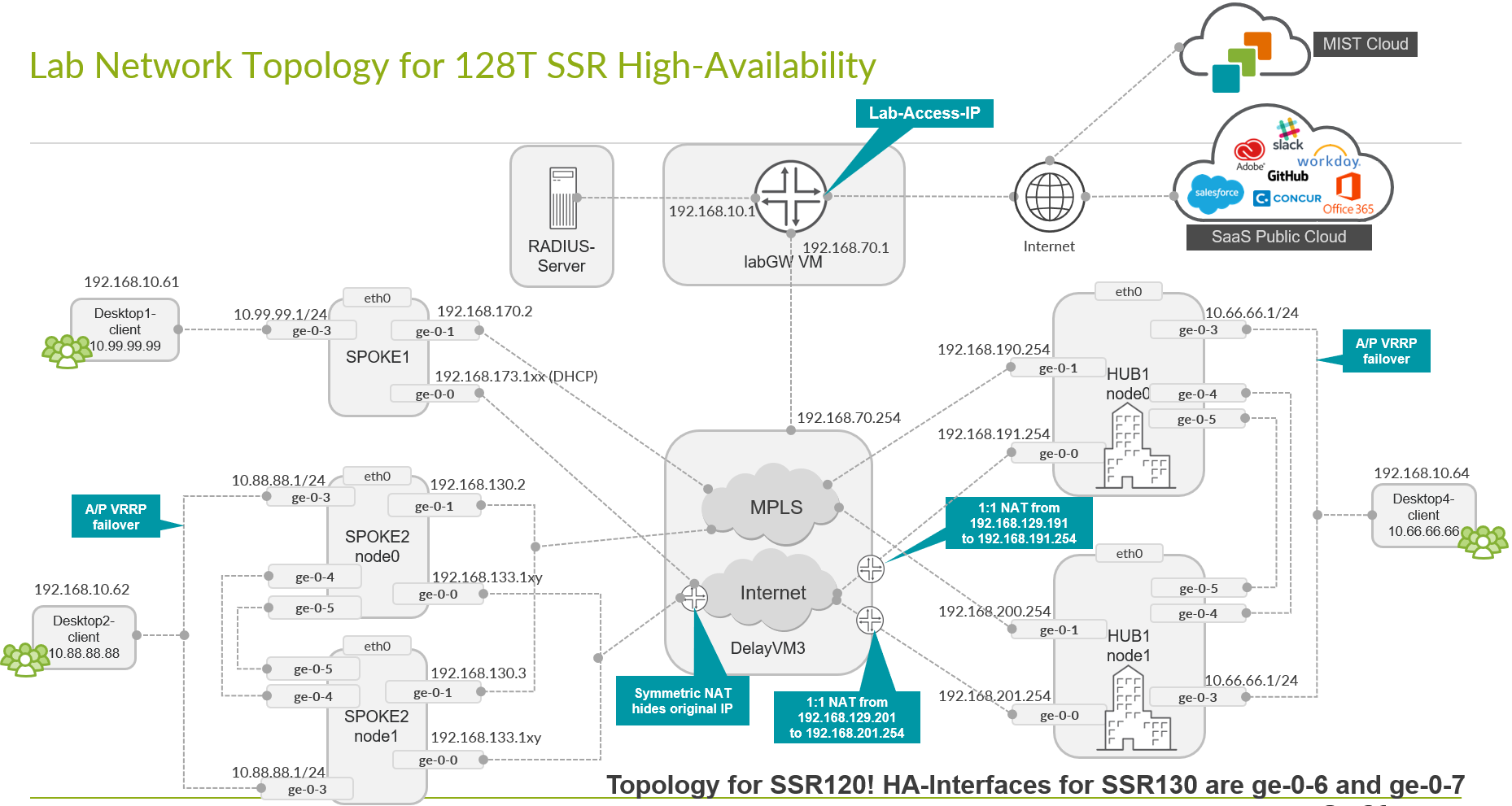
The topology for our example Lab is indicated in the below picture.
Configure Sites, Applications, Networks then clone Hub-Profile and Spokes-Template
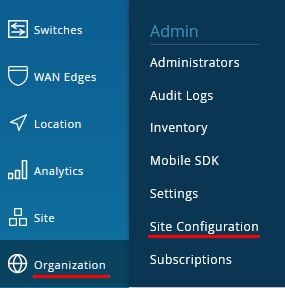
Go to Organization -> Site Configuration.
Click on “Create Site”-Button and create a Site called “hahub-site”. Add a proper location.
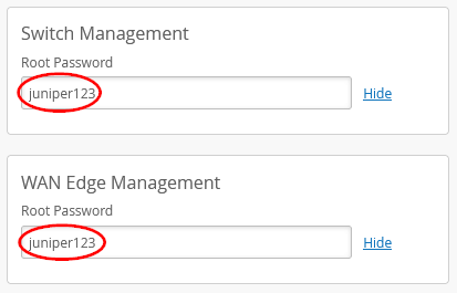
Make sure that in Site you configure the root password for Switch and WAN-Router Management!
Be sure to populate the root password for WAN Edges and Switches in the Site. The moment you activate a device to be managed by Mist Cloud it will set a random root password for security if you don’t define it.
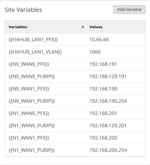
The variables we add are more or less a merger of the ones already used for the existing “hub1-site” and “hub2-site” but only one LAN-interface definition. So, add the below variables and values for that site.
| Site Name | Variable | Value |
| hahub-site | {{HAHUB_LAN1_PFX}} | 10.66.66 |
| hahub-site | {{HAHUB_LAN1_VLAN}} | 1066 |
| hahub-site | {{N0_WAN0_PFX}} | 192.168.191 |
| hahub-site | {{N0_WAN1_PFX}} | 192.168.190 |
| hahub-site | {{N0_WAN0_PUBIP}} | 192.168.129.191 |
| hahub-site | {{N0_WAN1_PUBIP}} | 192.168.190.254 |
| hahub-site | {{N1_WAN0_PFX}} | 192.168.201 |
| hahub-site | {{N1_WAN1_PFX}} | 192.168.200 |
| hahub-site | {{N1_WAN0_PUBIP}} | 192.168.129.201 |
| <hahub-site | {{N1_WAN1_PUBIP}} | 192.168.200.254 |
The result should look like the below.
“Save” your new site before you move on.
![]()
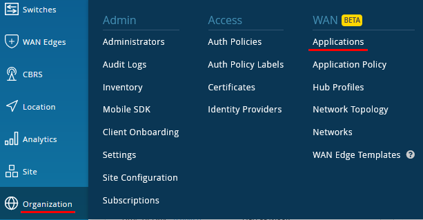
Go to Organization -> Applications.
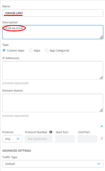
We configure a match criterion for all IP-Addresses attached at the LAN-Interface of the HAHub. Add an Application with the name set to “HAHUB-LAN1” and under IP-Addresses just configure the single IP-Prefix 10.66.66.0/24 for now.
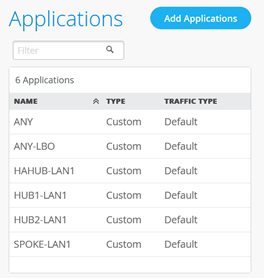
Your application overview should now look like this.
Go to Organization -> Networks.
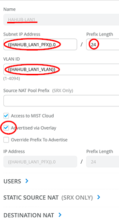
Configure a new network in the following way:
- Name=HAHUB-LAN1
- Subnet IP Address={{HAHUB_LAN1_PFX}}.0 this will substitute via site-variables that contain the first three octets.
- Prefix Length=24 (we hardcoded this)
- VLAN ID={{HAHUB_LAN1_VLAN}} to automatically use the right tag via site-variable.
- Make sure the default check box “Access to Mist Cloud” is set. We want possible future devices to be able to be managed by the Mist Cloud and have the right policy set.
- Activate the Check box “Advertised via Overlay”.
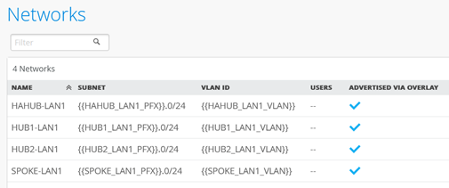
The resulting Networks overview should now look like the below
 <
<
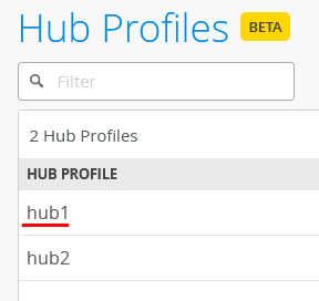
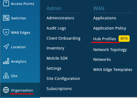
Go to Organization -> Hub Profiles
We create the new Hub-Profile by cloning the existing one and then modifying the clone. Hence click on the existing Profile “hub1”
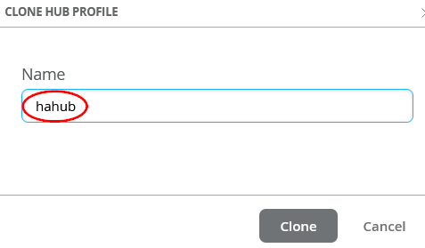
Then click on “Clone”

And name the new Profile “hahub”
BEST PRACTICE: Always refresh your Browser after you cloned something. This will make sure all objects are REALLY refreshed!
Graphical user interface, application

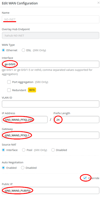
The new Profile now needs to be modified. Delete all exiting WAN-Interface that you have from the Clone and configure 4 new WAN-Interfaces. The first WAN-Interface configuration is as follows:
- Name=N0-INET this indicates which Topology it’s going to use.
- The Overlay Hub Endpoint will be automatically generated and should be “hahub-N0-INET”.
- As Interface=ge-0/0/0
- IP Address={{N0_WAN0_PFX}}.254
- Prefix Length=24
- Gateway={{N0_WAN0_PFX}}.1
- Source NAT=Enabled
- Check Override for Public IP
- Public IP={{N0_WAN0_PUBIP}}
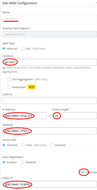
The second WAN-Interface configuration is as follows:
- Name=N0-MPLS this indicates which Topology it’s going to use.
- The Overlay Hub Endpoint will be automatically generated and should be “hahub-N0-MPLS”.
- As Interface=ge-0/0/1
- IP Address={{N0_WAN1_PFX}}.254
- Prefix Length=24
- Gateway={{N0_WAN1_PFX}}.1
- Source NAT=Enabled
- Check Override for Public IP
- Public IP={{N0_WAN1_PUBIP}}
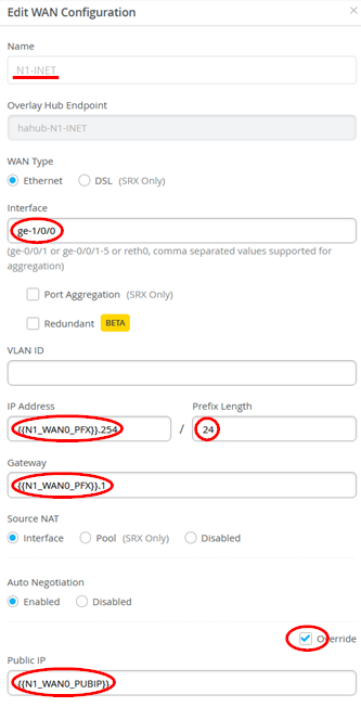
The third WAN-Interface configuration is as follows:
- Name=N1-INET this indicates which Topology it’s going to use.
- The Overlay Hub Endpoint will be automatically generated and should be “hahub-N1-INET”.
- As Interface=ge-1/0/0
- IP Address={{N1_WAN0_PFX}}.254
- Prefix Length=24
- Gateway={{N1_WAN0_PFX}}.1
- Source NAT=Enabled
- Check Override for Public IP
- Public IP={{N1_WAN0_PUBIP}}
The last WAN-Interface configuration is as follows:
- Name=N1-MPLS this indicates which Topology it’s going to use.
- The Overlay Hub Endpoint will be automatically generated and should be “hahub-N1-MPLS”.
- As Interface=ge-1/0/1
- IP Address={{N1_WAN1_PFX}}.254
- Prefix Length=24
- Gateway={{N1_WAN1_PFX}}.1
- Source NAT=Enabled
- Check Override for Public IP
- Public IP={{N1_WAN1_PUBIP}}
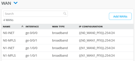
For the WAN-Interfaces and each node one should see and interface configuration for each interface as below.
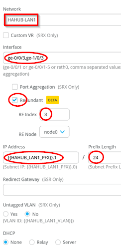
The LAN-Interface however needs to be defined as redundant interface for VRRP in the following way.
The LAN-Interface is also defined as redundant interface for cluster support.
- Network=HAHUB-LAN1
- Interfaces change to the added=ge-0/0/3,ge-1/0/3
- Redundant=Enabled
- RE Index=3 As a convention we usually use the last octet as index.
- IP Address={{HAHUB_LAN1_PFX}}.1
- Prefix=24 (did not change)
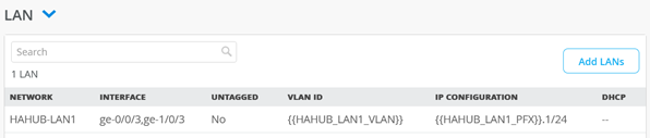
The overview of LAN-Interfaces should then look like this final result below
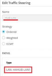
The Traffic steering rules need to be changed. The existing Rule for “HUB-LAN” need to be changed towards:
- Paths
- Type=LAN: HAHUB-LAN1
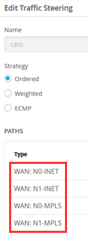
The existing Rule for “LBO” need to be changed towards:
- Paths
- Type=WAN: N0-INET
- Type=WAN: N1-INET
- Type=WAN: N0-MPLS
- Type=WAN: N1-MPLS
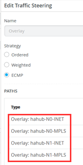
The existing Rule for “Overlay” need to be changed towards:
- Paths
- Type=Overlay: hahub-N0-INET
- Type=Overlay: hahub-N0-MPLS
- Type=Overlay: hahub-N1-INET
- Type=Overlay: hahub-N1-MPLS
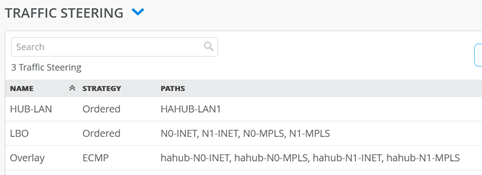
The Traffic steering rules now combine the interfaces of the two nodes and should look like below.
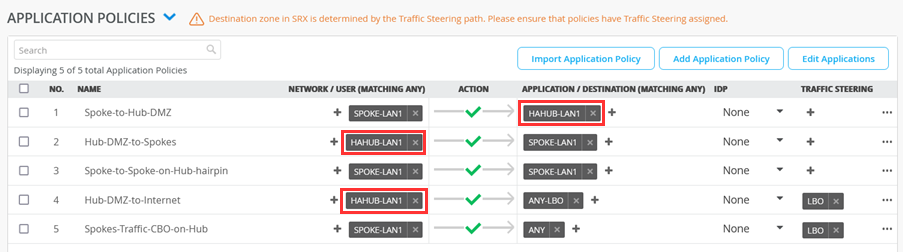
The Application Policies are VERY similar to the ones for hub1 or hub2. Basically you change where formally was HUB1-LAN1 to HAHUB-LAN1 . We indicate those changes below marked with Bold Font
| No. | Rule Name | Network | Action | Destination | Steering |
| 1 | Spoke-to-Hub-DMZ | SPOKE-LAN1 | Pass | HAHUB-LAN1 | N/A |
| 2 | Hub-DMZ-to-Spokes | HAHUB-LAN1 | Pass | SPOKE-LAN1 | N/A |
| 3 | Spoke-to-Spoke-on-Hub-hairpin | SPOKE-LAN1 | Pass | SPOKE-LAN1 | N/A |
| 4 | Hub-DMZ-to-Internet | HAHUB-LAN1 | Pass | ANY-LBO | LBO |
| 5 | Spokes-Traffic-CBO-on-Hub | SPOKE-LAN1 | Pass | ANY | LBO |
Below is an overview of the made changes.
We now need to create two matching Spoke Templates where one Spoke is in standalone mode and the other in HA-Cluster as well.
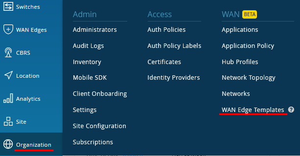
Go to Organization -> WAN Edge Templates.
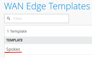
We create the new Spoke-Template by cloning the existing one and then modifying the clone. Hence click on the existing Profile “Spokes”
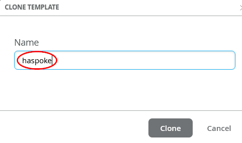
Then click on “Clone”
And name the new Profile “haspoke”
BEST PRACTICE: Always refresh your Browser after you cloned something. This will make sure all objects are REALLY refreshed!
Graphical user interface, application
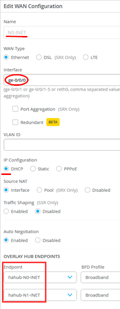
We now need to change our clone Template. Remove all older WAN interfaces and configure the following four WAN-Interfaces. The first WAN-Interface configuration is as follows:
- Name=N0-INET this indicates which Topology it’s going to use.
- WAN Type=Ethernet
- As Interface=ge-0/0/0
- IP Configuration=DHCP
- Overlay Hub Endpoints
- Endpoint1=hahub-N0-INET
- Endpoint2=hahub-N1-INET
The second WAN-Interface configuration is as follows:
- Name=N0-MPLS this indicates which Topology it’s going to use.
- WAN Type=Ethernet
- As Interface=ge-0/0/1
- IP Configuration=STATIC
- IP Address={{WAN1_PFX}}.2
- Prefix=24
- Gateway={{WAN1_PFX}}.1
- Overlay Hub Endpoints
- Endpoint1=hahub-N0-MPLS
- Endpoint2=hahub-N1-MPLS

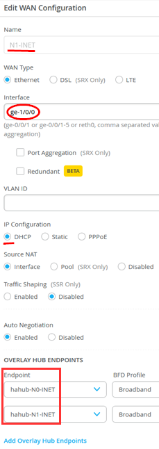
The third WAN-Interface configuration is as follows:
- Name=N1-INET this indicates which Topology it’s going to use.
- WAN Type=Ethernet
- As Interface=ge-1/0/0
- IP Configuration=DHCP
- Overlay Hub Endpoints
- Endpoint1=hahub-N0-INET
- Endpoint2=hahub-N1-INET
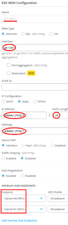
The last WAN-Interface configuration is as follows:
- Name=N1-MPLS this indicates which Topology it’s going to use.
- WAN Type=Ethernet
- As Interface=ge-1/0/1
- IP Configuration=STATIC
- IP Address={{WAN1_PFX}}.3
- Prefix=24
- Gateway={{WAN1_PFX}}.1
- Overlay Hub Endpoints
- Endpoint1=hahub-N0-MPLS
- Endpoint2=hahub-N1-MPLS
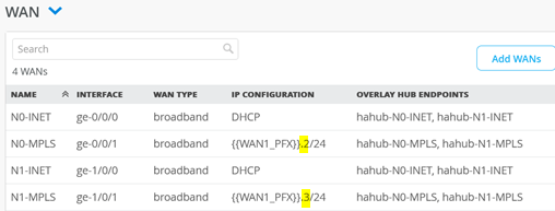
For the WAN-Interfaces and each node one should see and interface configuration for each interface as below. In our case the Internet interfaces get a DHCP-Lease each and the MPLS interfaces have a different static IP-Address in the same subnet.
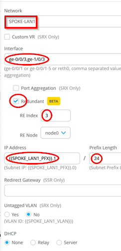
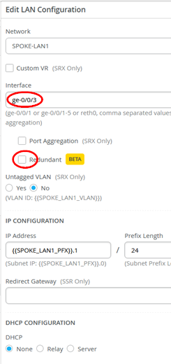
The LAN-Interface however needs to be defined as redundant interface for VRRP. You need to edit the existing LAN interface SPOKE-LAN1 as below
- Network=SPOKE-LAN1
- Interfaces change to the added=ge-0/0/3,ge-1/0/3
- Redundant=Enabled
- RE Index=3 As a convention we usually use the last octet as index.
- IP Address={{SPOKE_LAN1_PFX}}.1
- Prefix=24 (did not change)
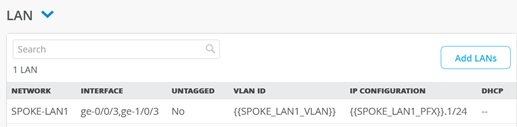
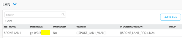
The resulting overview of LAN interfaces should look like below
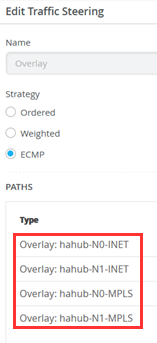
The Traffic steering rules now need to combine the interfaces of the two HA-nodes. Hence, the existing Rule for “Overlay” need to be changed towards:
- Paths
- Type=Overlay: hahub-N0-INET
- Type=Overlay: hahub-N0-MPLS
- Type=Overlay: hahub-N1-INET
- Type=Overlay: hahub-N1-MPLS
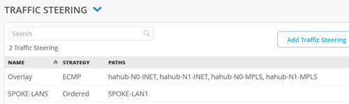
The overview of the Traffic Steering Rule Set should now look like the below.
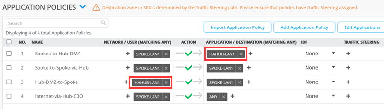
The Application Policies are VERY similar to the ones for Spokes. We have indicated the changes you need to make below Bold Font
| No. | Rule Name | Network | Action | Destination | Steering |
| 1 | Spoke-to-Hub-DMZ | SPOKE-LAN1 | Pass | HAHUB-LAN1 | N/A |
| 2 | Spoke-to-Spoke-via-Hub | SPOKE-LAN1 | Pass | SPOKE-LAN1 | N/A |
| 3 | Hub-DMZ-to-Spoke | HAHUB-LAN1 | Pass | SPOKE-LAN1 | N/A |
| 4 | Internet-via-Hub-CBO | SPOKE-LAN1 | Pass | ANY | N/A |
Below is an overview of the made changes.
Now click on the “Assign to Sites”-Button
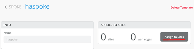
Check that you are using the “haspoke” Template and select the site “spoke2-site” before you hit “Apply”.
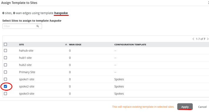
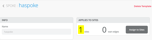
Check that your Template has now at least 1 Site assigned.
Go to Organization -> WAN Edge Templates.
We create the new Spoke-Template by cloning the existing one and then modifying the clone. Hence click on the existing Profile “haspoke”

Then click on “Clone”
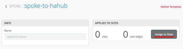
And name the new Profile “spoke-to-hahub”

BEST PRACTICE: Always refresh your Browser after you cloned something. This will make sure all objects are REALLY refreshed!
Graphical user interface, application
There are not many differences between this and the former template. You just have one single node with only two WAN-Interfaces so please configure the WAN-Interfaces
- Delete the existing WAN-Interface Name=N1-INET
- Delete the existing WAN-Interface Name=N1-MPLS
The result should now look like the below

The LAN-Interfaces are no longer redundant. To archive this configure:
- Change the Interface=ge-0/0/3
- Change Redundant=Disabled
The result should look like this
Traffic steering rules and Application Policies are the same as in the last Template and do not need to be changed.
Now click on the “Assign to Sites”-Button
Check that you are using the “spoke-to-hahub” Template and select the site “spoke1-site” before you hit “Apply”.
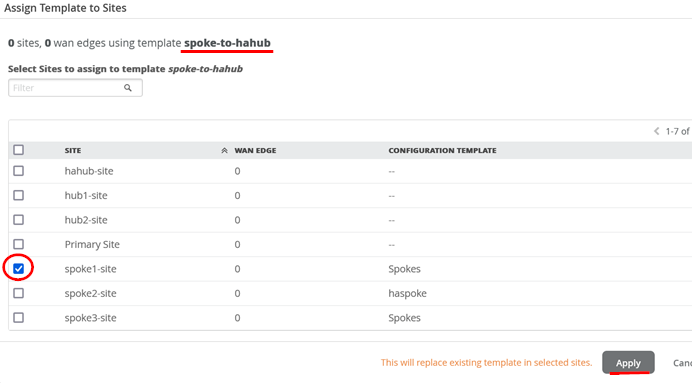
Check that your Template has now at least 1 Site assigned.
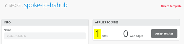
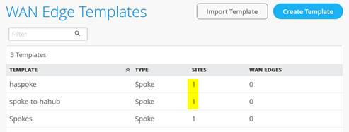
Your WAN-Ede Template overview should now look like the below. Please check.
Onboard your Devices
Now it’s time to use the Claim or Adopt Method to onboard the devices and see them in the organization inventory. We have already shared this information in chapter 2 above as it is a Day-0 task. On-board your devices please and then continue here.
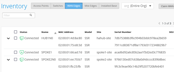
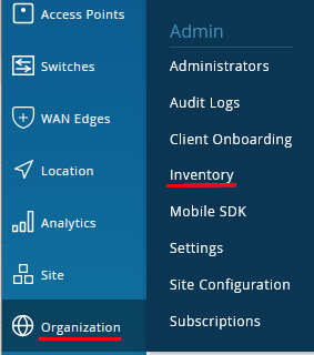
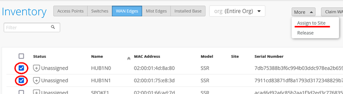
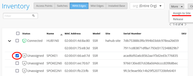
Go to Organization -> Inventory
Make sure the Inventory-View is set to “(Entire Org)” as below and hit the refresh-Button on your Browser until you hopefully see all your devices.
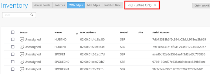
Select the TWO devices/nodes at the same time for the HA-hub and “Assign to Site”.
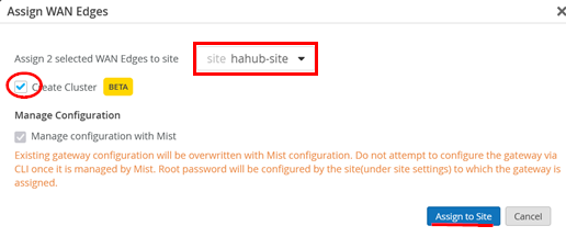
Select “hahub-site” and enable “Create Cluster” before you “Assign to Site”.
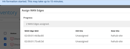
Close the dialogue
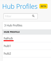
Go to Organization -> Hub Profiles
Select the Profile “hahub”
Under “Applies To” select “hahub-site” and the hub-device in that site.
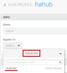
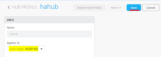
Check if you have the right WAN-Edge device and “Save”.
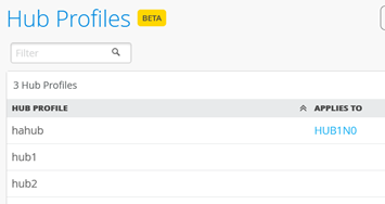
You should now see the HA-devices assigned to their Profile in the overview.
Go back to Organization -> Inventory
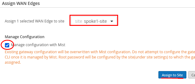
Select the proper device for the first Spoke and “Assign to Site”.
Select “spoke1-site” and enable “Manage configuration with Mist” before you “Assign to Site”.
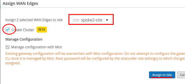
Select the two devices that will belong to the Spoke-Cluster same time and execute “Assign to Site”.

Select “spoke2-site” and enable “Create Cluster” before you “Assign to Site”.
Instead of one you should now have assigned two devices to the site.
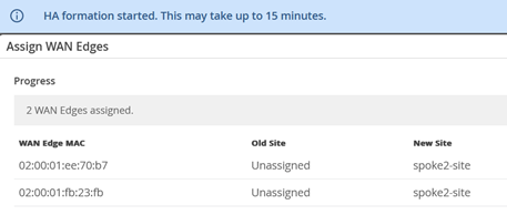
After a while waiting (and refreshing the Browser) you should see something like this.