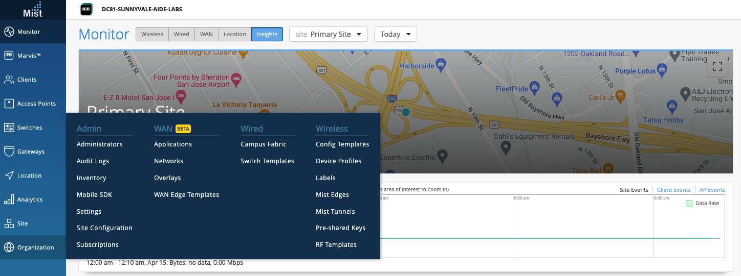
Select the Campus Fabric option, under the Wired Section of the Organization Tab:
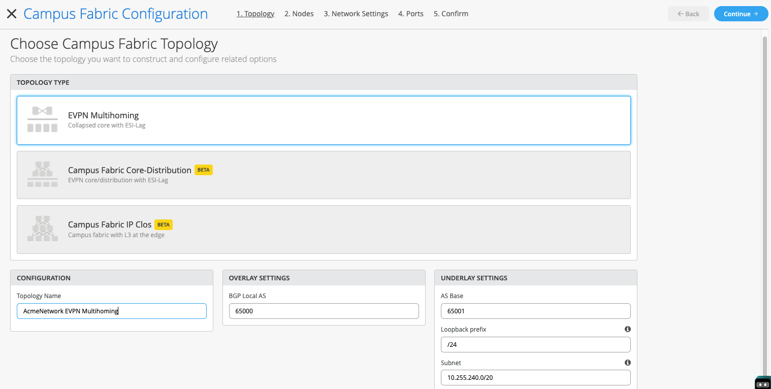
Select EVPN Multihoming and complete the required fields below (default settings suffice):
- Topology Name: The configuration name should represent the Campus Fabric being deployed
- Overlay Settings: Define the BGP AS used to build the Overlay between the Collapsed Core switches
- Underlay Settings: AS Base # used to build the underlay between the Collapsed Core switches. Loopback Prefix # is the subnet defining the number of hosts in the loopback subnet.
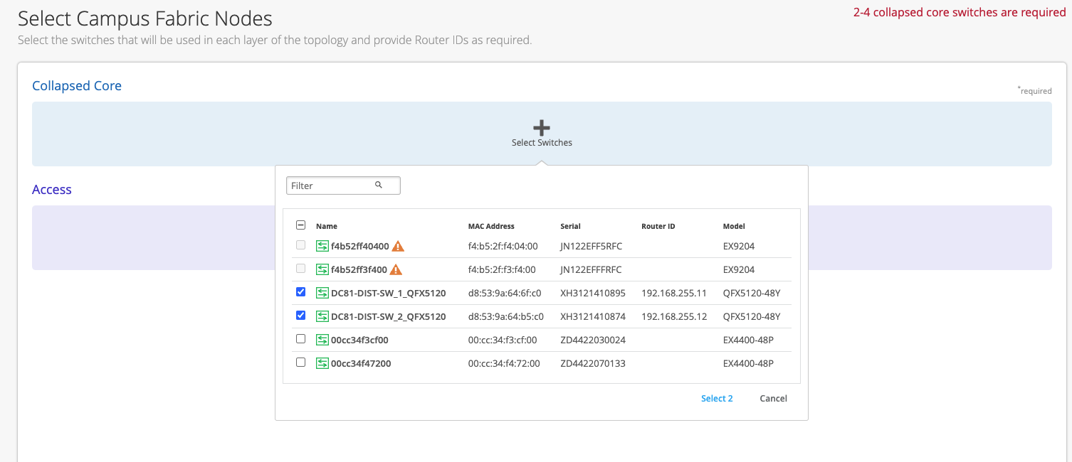
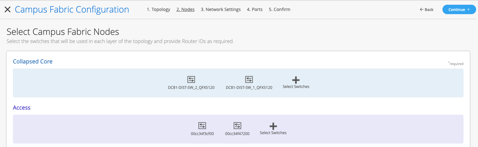
Start by selecting the 2 Collapsed Core switches, in this case we select the 2 QFX 5120-48Y platforms
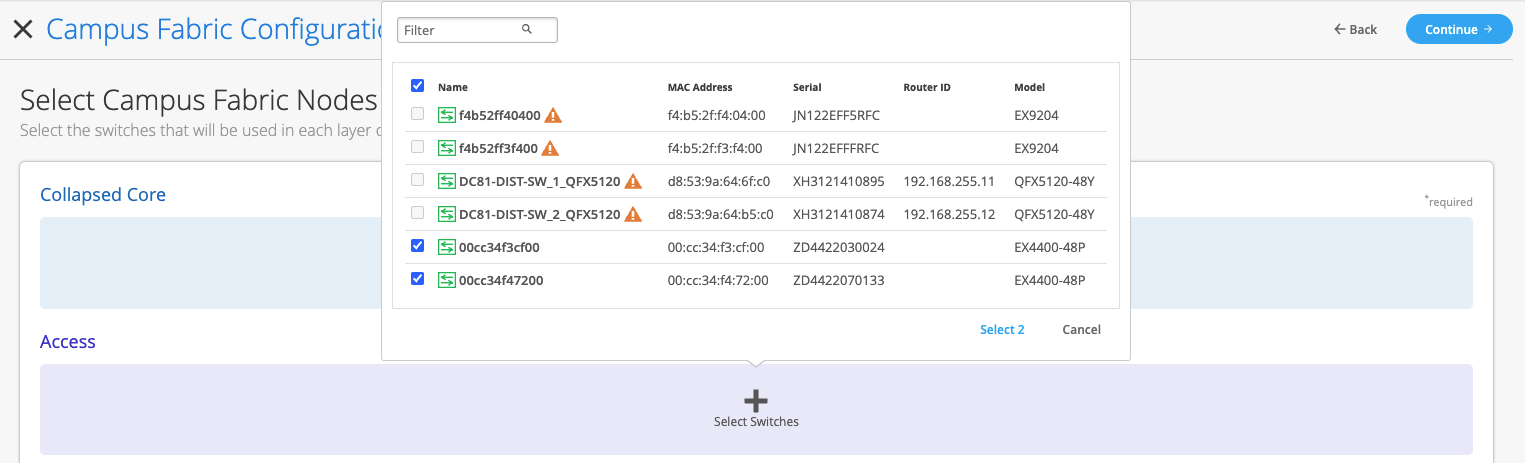
Next, select the Access switches from the drop-down list. Here, we select the 2 EX4400-48P platforms.
Once all switches have been selected, the Mist UI presents the following:
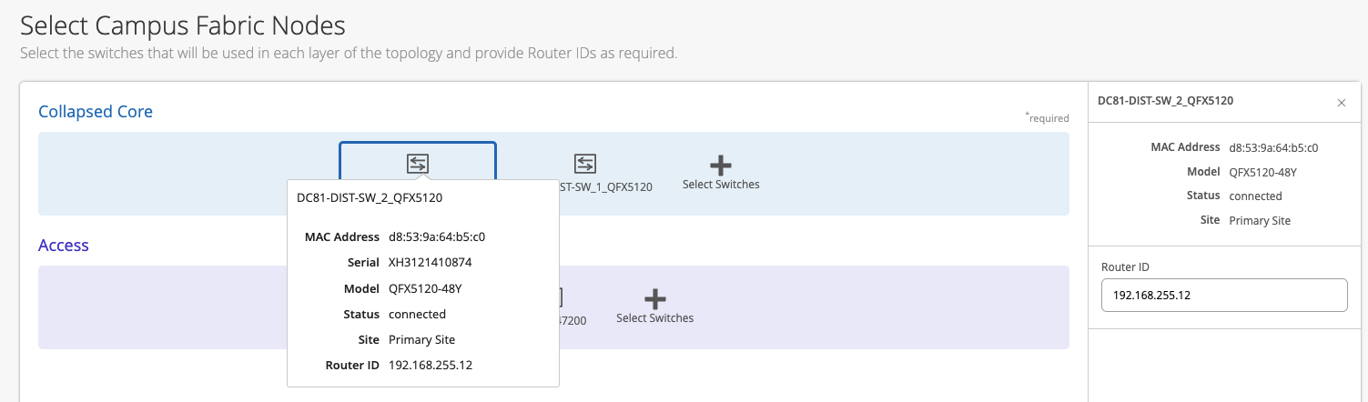
If these devices are being installed for the first time or have not been deployed to date, each Collapsed Core will need a Router ID assigned. The Router ID is used as an identifier when deploying routing protocols such as BGP. In this case, we have existing Router IDs associated with both Collapsed Core platforms show when clicking each Icon. Mist UI also provides chassis information per each platform when clicking the device Icon. The following displays the second Collapsed Core switch’s information including the existing Router ID:
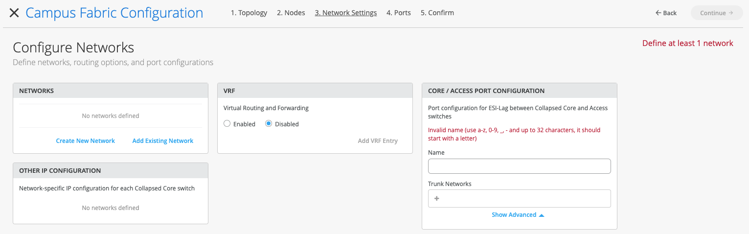
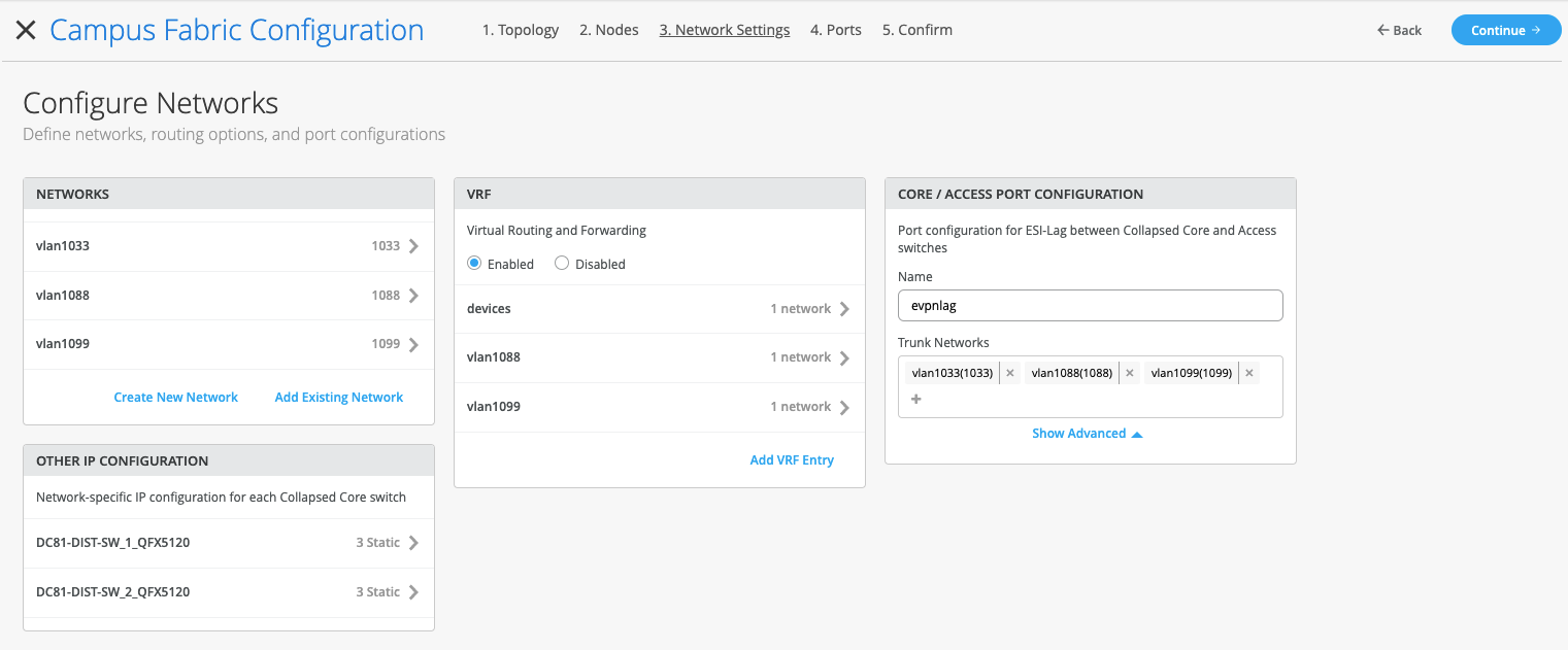
Now we are ready to move to the Network Settings section of the EVPN Multihoming Deployment process by clicking the Continue Button at the upper right-hand corner of the page. The Configure Networks section defines the networks, routing options, and port configurations:
One of the benefits of the Mist UI is the ability to predefine Networks before the EVPN Multihoming deployment. In this case, we select the “AcmeEVPN-MH” Networks template which prepopulates the VLANs that are part of the EVPN Multihoming build.
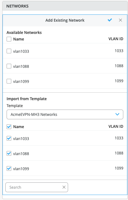
Once the VLANs are selected, click the check mark at the upper right-hand corner of the drop-down.
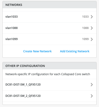
The Mist UI provides the following deployment options:
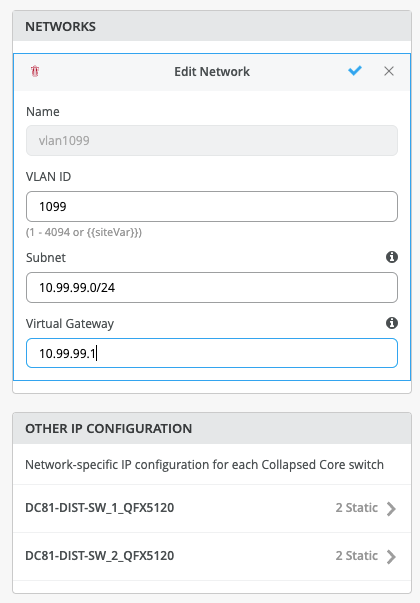
- Configuration of the Subnet/Virtual Gateway instructs the device that it will be acting as the Default Gateway for the specific VLAN/subnet.
- Leaving these options blank allows a 3rd party device such as a Firewall to be used as the Default Gateway or next hop for each VLAN. This allows support for granulate security policies to be implemented where applicable.
- Juniper supports the ability to mix and match requirements – for example, some networks may terminate locally on the core and some may transit to a firewall for inspection
In this case, we assign VLAN IDs, Subnet addresses and Virtual Gateways to each VLAN selected. In this example, we highlight the data per VLAN 1099:
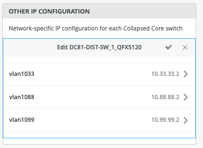
Once all VLANs have been configured, each Collapsed Core switch is automatically assigned IP addresses in each VLAN while sharing the Virtual Gateway address, typically used as a Default Gateway address for each VLAN. The following highlights one of the Collapsed Core’s IP addressing for each VLAN:
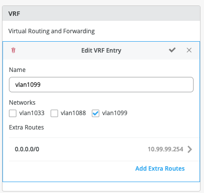
In this example, we choose to isolate each VLAN in its own virtual routing instance. This is due to ACME’s requirement for PCI and granular security policy implementation between VLANs. Under the VRF tab, create a new VRF entry, then associate which VLAN(s) are included in the VRF and if additional routing is required. For example, ACME has decided to utilize an existing Juniper SRX firewall to route between each isolated VRF. This satisfies their security policy enforcement guidelines for traffic patterns between VLANs.
The following illustrates the configuration for VRF named vlan1099. Select the checkmark at the upper right-hand corner of the tab to complete the configuration for each VRF:
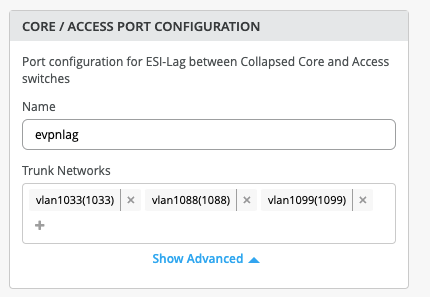
Create the ESI LAG port configuration between Collapsed Core switches and Access switches. Use a lowercase naming structure and insure all 3 VLANs are associated:
Inspect each Tab for accuracy before clicking the Continue button. The Mist UI provides the ability to go back to various screens if needed:
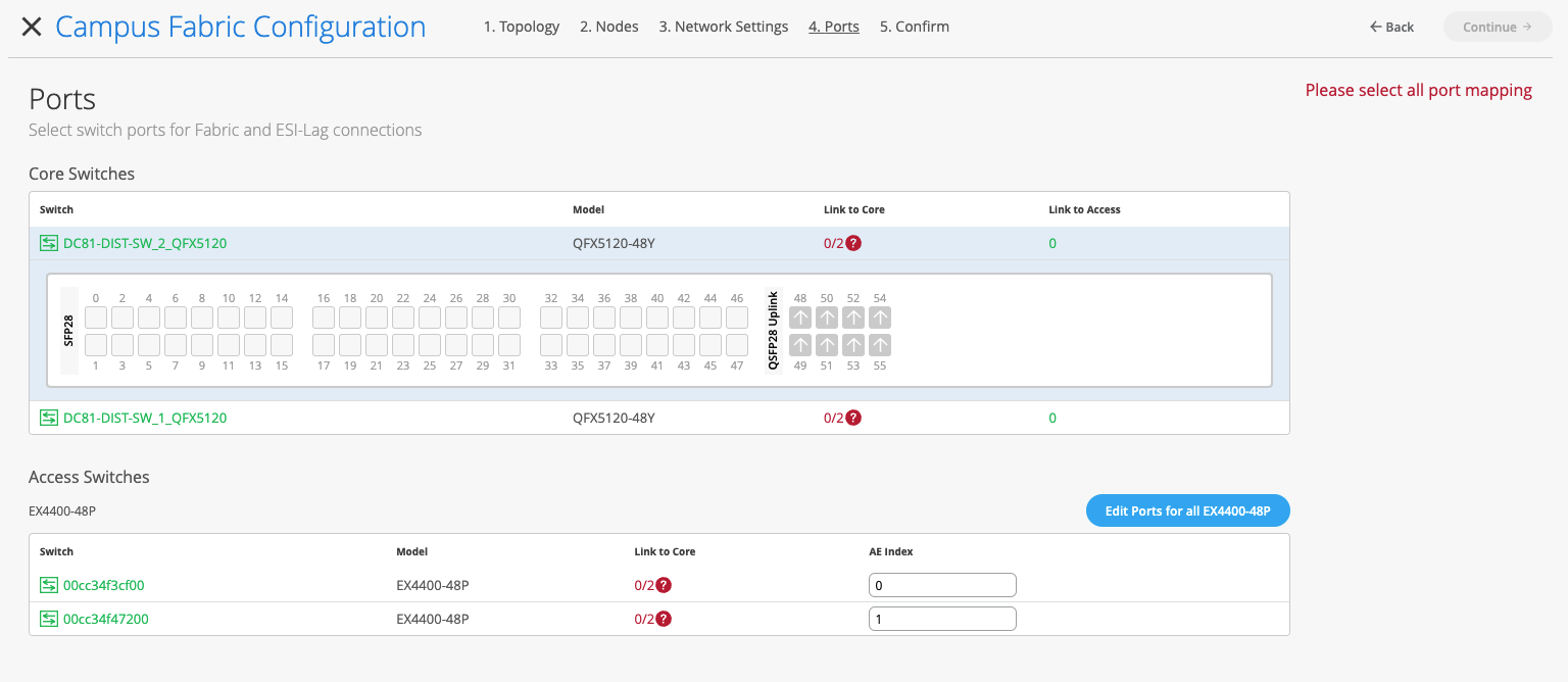
We are in the final stages of deploying the EVPN Multihoming Campus Fabric by selecting which ports are associated between the Collapsed Core switches and between the Collapsed Core and Access switches
The first step is to select the ports that interconnect each Collapsed Core switch. Assuming all devices are interconnected properly, we can utilize LLDP data per each switch to ascertain port connectivity. For example, the following displays devices connected to Collapsed Core SW1 by selecting the remote shell option under the Utilities section of the switch:
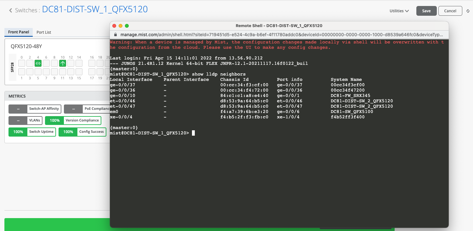
Note: To ensure accuracy, Juniper recommends each this task is performed on all switches involved in the EVPN MH Campus Fabric.
We are now ready to select the ports that interconnect the Collapsed Core Switches.
Select each of the core ports off SW1 that connect to SW2.
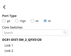
Ensure Link to Core and the proper port type are selected. In this case, et-0/0/46-47:
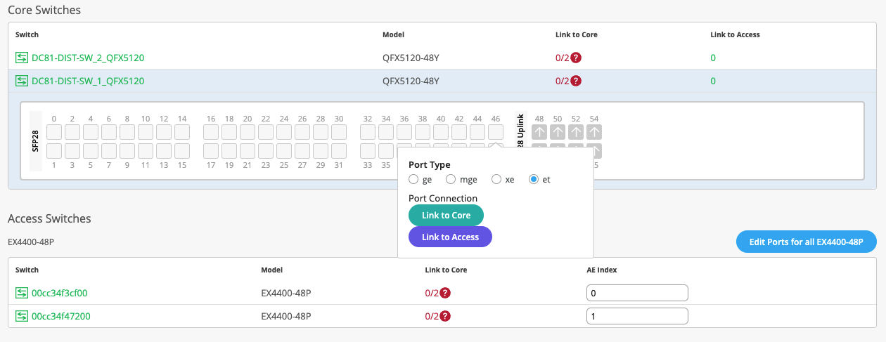
From here, select which local port corresponds to each remote port between Collapsed Cores:
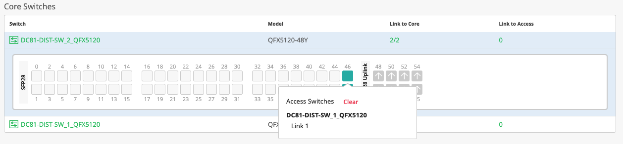
Core ports are shown below, allowing the administrator to clear the selection if needed.
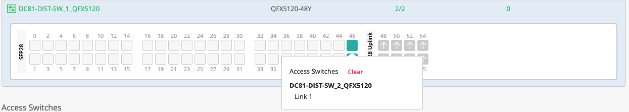
Complete this exercise for the second Collapsed Core and verify:
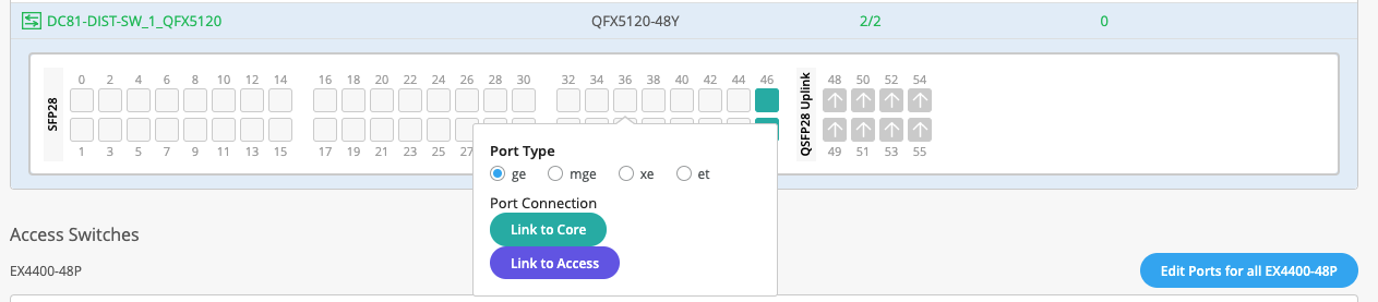
Now select the ports that connect each Collapsed Core switch to each Access Switch.
In this case, SW1 utilizes ge-0/0/36 to connect to Access 1 and ge-0/0/37 to Access 2.
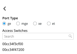
Select ge-0/0/36, Link to Access and port type “ge” then choose the correct Access Switch.
Perform this for both ports.
The same procedure applies for each Access switch.
It is not necessary to know the Collapsed Core remote ports when selecting these uplink ports.
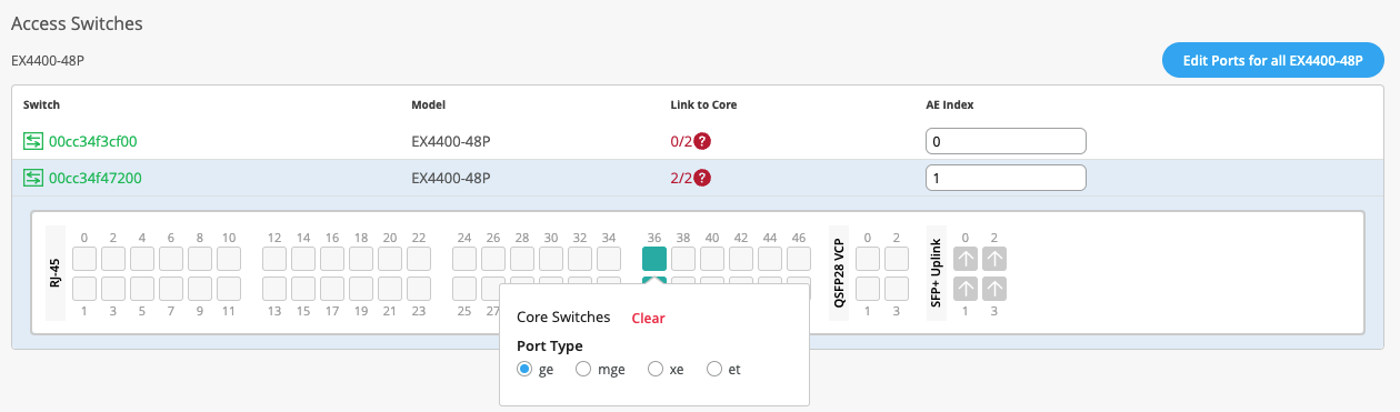
Note: It is recommended to utilize AE Bundles 0 and 1 respectively per each Access switch if this is a new installation.
Once all ports have been selected and verified, click the Continue option.
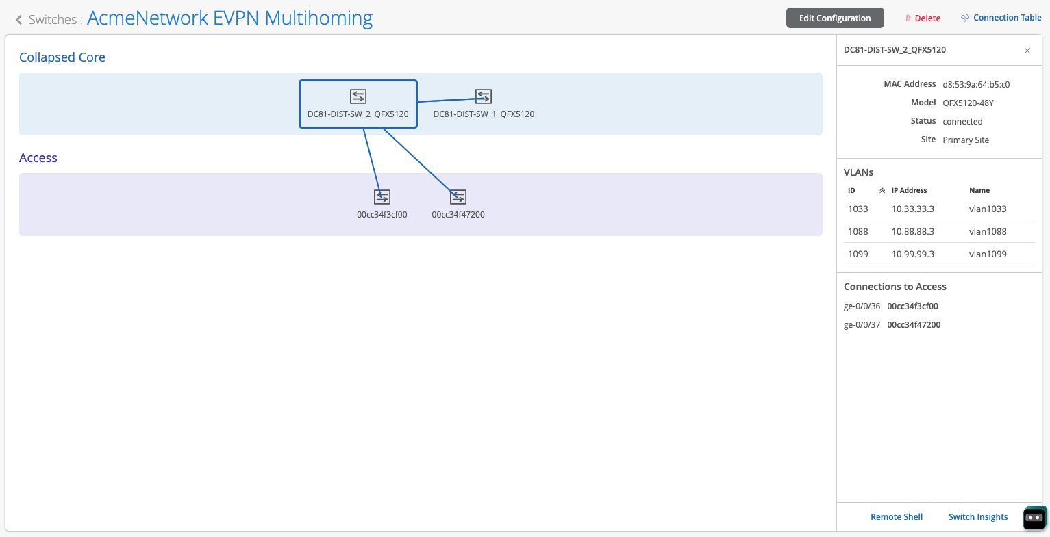
Confirmation of the EVPN Multihoming Build is shown below. Clicking each platform displays the physical toplogy with requisite data on the right section of the page. Notice, the administrator can access each device through the remote shell option at the lower right corner:
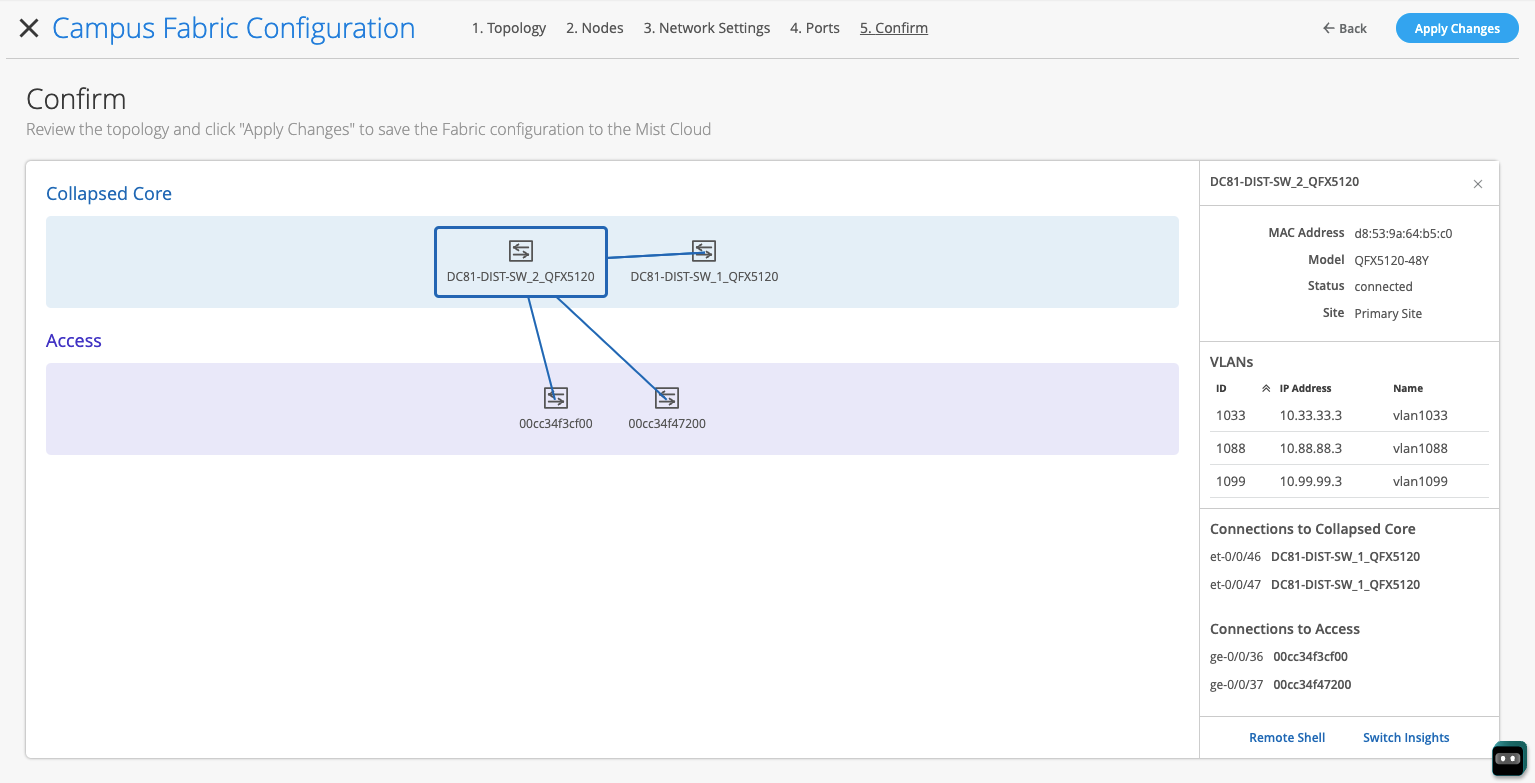
Note: Juniper recommends verification of the EVPN Multihoming Fabric by selecting each switch’s output.
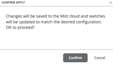
Once all verification is complete, select the Apply Changes option at the right-hand corner of the page. The Mist UI provides the following disclaimer that this new configuration will be applied accordingly:
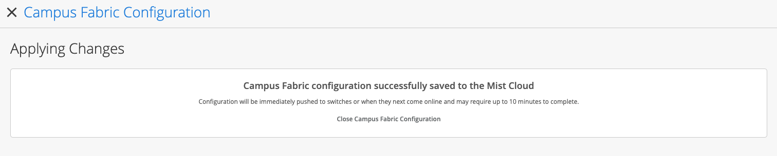
Finally, the Campus Fabric configuration has been saved to the Mist Cloud which can take up to 10 minutes to complete the configuration push to all elements:
Closing the Campus Fabric Configuration brings the administrator to the Campus Fabric section of the Mist UI.
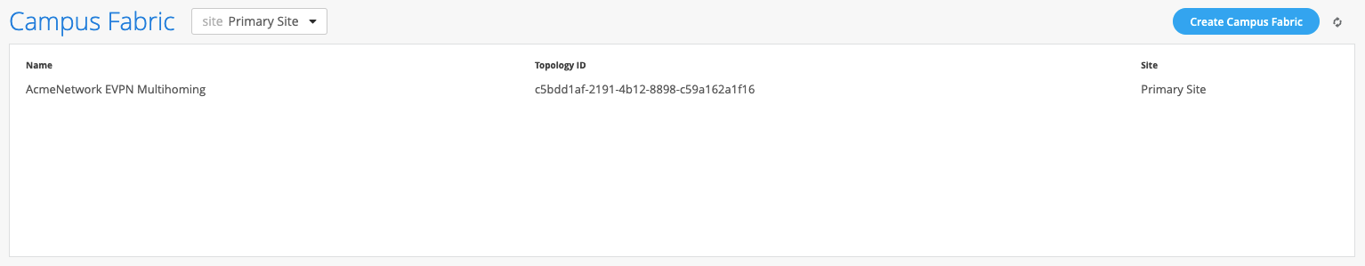
The user can now access the EVPN Multihoming Campus Fabric:
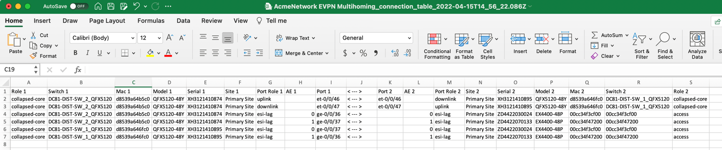
Notice the Connection Table option at the upper right corner. This provides a layout of the EVPN Multihoming topology as configured and can be used as a source of truth with respect to device interconnectivity parameters:
Supported Platforms
Collapsed Core
- EX4100*
- EX4300-MP
- EX4400*
- EX4650*
- QFX5120*
- EX9204, 9208, 9214
- QFX10000*
Access
- EX2300*
- EX3400*
- EX4100*
- EX4300*
- EX4400*
- EX4650*
- QFX5110*
- QFX5120*