Technology Primer: Campus Fabric IP Clos
Use Case Overview
Enterprise networks are undergoing massive transitions to accommodate the growing demand for cloud-ready, scalable, and efficient networks, and the plethora of IoT (Internet of Things) and mobile devices. As the number of devices grows, so does network complexity with an ever-greater need for scalability, segmentation, and security. To meet these challenges, you need a network with Automation and AI (Artificial Intelligence) for operational simplification. IP Clos networks provide increased scalability and segmentation using a well-understood standards-based approach (EVPN-VXLAN with GBP).
Most traditional campus architectures use single-vendor, chassis-based technologies that work well in small, static campuses with few endpoints. However, they are too rigid to support the scalability and changing needs of modern large enterprises. MC-LAG (multi-chassis link aggregation group) is a good example of a single-vendor technology that addresses the collapsed core deployment model. In this model, 2 chassis-based platforms are typically in the core of a customer’s network; deployed to handle all L2/L3 requirements while providing an active/backup resiliency environment. MC-LAG does not interoperate between vendors, creating lock-in, and is limited to 2 devices.
A Juniper Networks EVPN-VXLAN fabric is a highly scalable architecture that is simple, programmable, and built on a standards-based architecture (https://www.rfc-editor.org/rfc/rfc8365) that is common across campuses and data centers.
The Juniper campus architecture uses a Layer 3 IP-based underlay network and an EVPN-VXLAN overlay network. Broadcast, unknown unicast, and multicast, commonly known as BUM (Broadcast, Unknown unicast, and Multicast) traffic, is handled natively by EVPN and eliminates the need for Spanning Tree Protocols (STP/RSTP). A flexible overlay network based on a VXLAN tunnels combined with an EVPN control plane efficiently provides Layer 3 or Layer 2 connectivity. This architecture decouples the virtual topology from the physical topology, which improves network flexibility and simplifies network management. Endpoints that require Layer 2 adjacency, such as IoT devices, can be placed anywhere in the network and remain connected to the same logical Layer 2 network.
With an EVPN-VXLAN campus architecture, you can easily add core, distribution, and access layer devices as your business grows without having to redesign the network. EVPN-VXLAN is vendor-agnostic, so you can use the existing access layer infrastructure and gradually migrate to access layer switches that support EVPN-VXLAN capabilities once the Core and Distribution part of the network is deployed. Connectivity with legacy switches that do not support EVPN VXLAN is accomplished with standards-based ESI-LAG. ESI-LAG utilizes standards-based LACP (Link Aggregation Control Protocol) to interconnect with legacy switches.
Benefits of Campus Fabric: IP Clos
With the increasing number of devices connecting to the network, you will need to scale your campus network rapidly without adding complexity. Many IoT devices have limited networking capabilities and require Layer 2 adjacency across buildings and campuses. Traditionally, this problem was solved by extending VLANs between endpoints using data plane-based flood and learning mechanisms inherent with ethernet switching technologies. The traditional ethernet switching approach is inefficient because it leverages broadcast and multicast technologies to announce MAC (Media Access Control) addresses. It is also difficult to manage because you need to manually configure VLANs to extend them to new network ports. This problem increases multi-fold when considering the explosive growth of mobile and IoT devices.
Campus fabrics have an underlay topology with a routing protocol that ensures loopback interface reachability between nodes. Devices participating in EVPN-VXLAN function as VTEPs (VXLAN Tunnel Endpoint) that encapsulate and decapsulate the VXLAN traffic. VTEP (VXLAN Tunnel Endpoint) stands for VXLAN tunnel endpoint and represents the construct within the switching platform that originates and terminates VXLAN tunnels. In addition, these devices route and bridge packets in and out of VXLAN tunnels as required.
The Campus Fabric IP Clos extends the EVPN fabric to connect VLANs across multiple buildings or floors of a single building, by stretching the Layer 2 VXLAN network with routing occurring in the access device instead of the Core or Distribution layers. IP Clos network encompasses the distribution, core, and access layers of your topology.
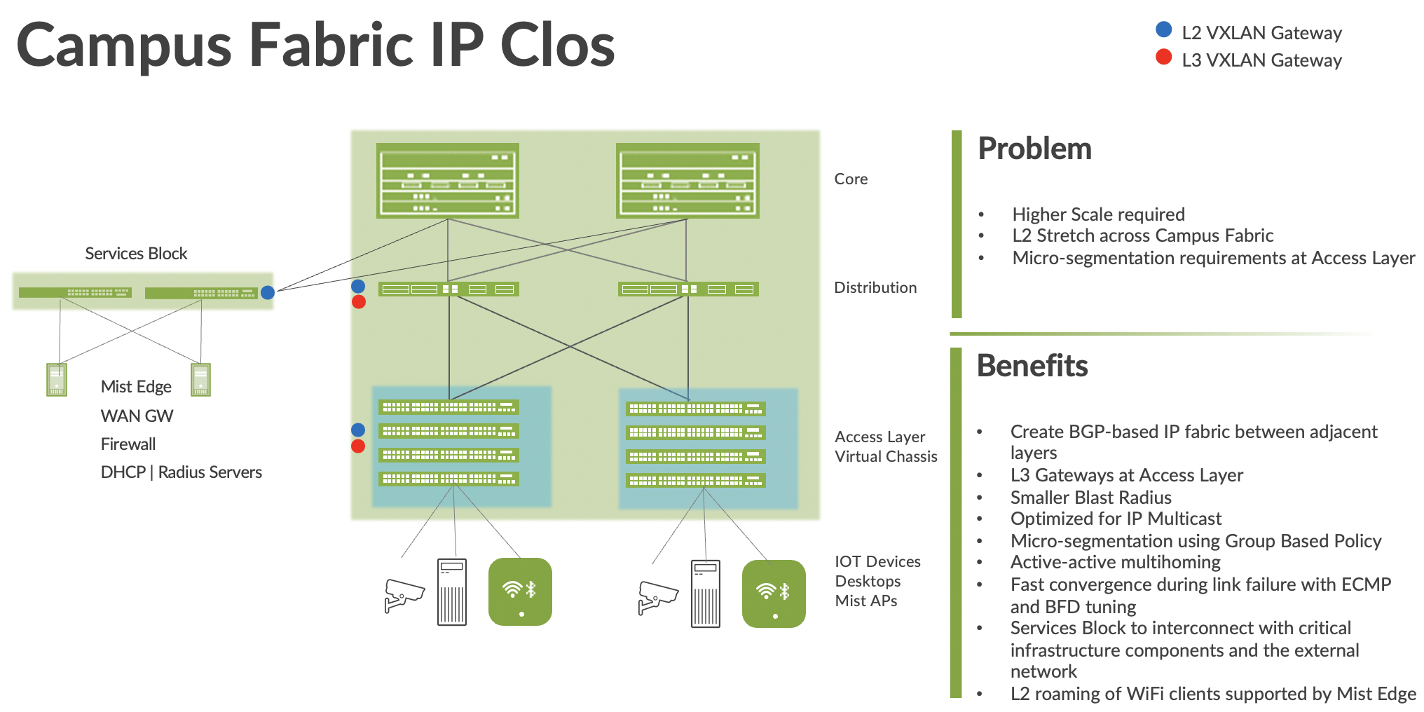
Figure 1 Campus fabric IP Clos
An EVPN-VXLAN fabric solves the problems of previous architectures and provides the following benefits:
- Reduced flooding and learning—Control plane-based Layer 2/Layer 3 learning reduces the flood and learn issues associated with data plane learning. Learning MAC addresses in the forwarding plane has an adverse impact on network performance as the number of endpoints grows. This is because more management traffic consumes the bandwidth which leaves less bandwidth available for production traffic. The EVPN control plane handles the exchange and learning of MAC addresses through eBGP routing, rather than a Layer-2 forwarding plane.
- Scalability—More efficient control-plane based Layer 2/Layer 3 learning. For example, in a Campus Fabric IP Clos, core switches do not learn the device endpoint addresses, rather they only learn the addresses of the Access layer switches.
- Consistency—A universal EVPN-VXLAN-based architecture across disparate campus and data-center deployments enables a seamless end-to-end network for endpoints and applications.
- Group Based Policies – With GBP you can enable micro-segmentation with EVPN-VXLAN to provide traffic isolation within and between broadcast domains as well as simplify security policies across a Campus Fabric.
Location-agnostic connectivity—The EVPN-VXLAN campus architecture provides a consistent endpoint experience no matter where the endpoint is located. Some endpoints require Layer 2 reachability, such as legacy building security systems or IoT devices. VXLAN overlay provides Layer 2 extension across campuses without any changes to the underlay network. Juniper uses optimal BGP timers between the adjacent layers of the Campus Fabric with BFD (Bidirectional Forwarding Detection) (fast convergence in case of a node or link failure) and ECMP (Equal cost multipath). https://www.juniper.net/documentation/us/en/software/junos/sampling-forwarding-monitoring/topics/concept/policy-configuring-per-packet-load-balancing.html
Technical Overview
Underlay Network
An EVPN-VXLAN fabric architecture makes the network infrastructure simple and consistent across campuses and data centers. All the core, distribution, and access devices must be connected to each other using a Layer 3 infrastructure. Juniper recommends deploying a Clos-based IP fabric to ensure predictable performance and to enable a consistent, scalable architecture.
Layer 3 routing protocols are used to exchange loopback addresses between the access, core, and distribution devices. BGP provides benefits like better prefix filtering, traffic engineering, and route tagging. We are using eBGP as the underlay routing protocol in this example. Mist automatically provisions Private Autonomous System numbers and all BGP configuration for the underlay and overlay for only the campus fabric. There are options to provision additional BGP speakers to allow customers to peer with external BGP peers.
Underlay BGP is used to learn loopback addresses from peers enabling the overlay BGP can establish neighbors using the loopback address. The overlay is then used to exchange EVPN routes.
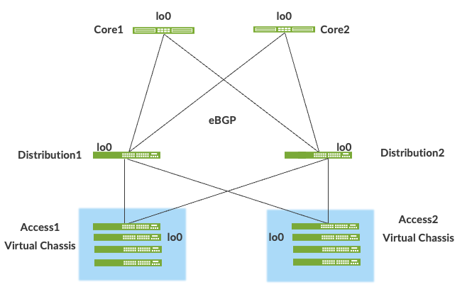
Figure 2. Pt-Pt /31 links between adjacent layers running eBGP
Network overlays enable connectivity and addressing independent of the physical network. Ethernet frames are wrapped in IP UDP datagrams that are themselves encapsulated into IP for transport over the underlay. VXLAN enables virtual Layer 2 subnets (or VLANs) to span underlying physical Layer 3 network.
In a VXLAN overlay network, each Layer 2 subnet or segment is uniquely identified by a virtual network identifier (VNI). A VNI segments traffic the same way that a VLAN ID does. This mapping occurs on the Access switches and Border Gateway, which could reside on the Core or Services Block. As is the case with VLANs, endpoints within the same virtual network can communicate directly with each other.
Endpoints in different virtual networks require a device that supports inter-VXLAN routing, which is typically a router, or a high-end switch known as a Layer-3 gateway. The entity that performs VXLAN encapsulation and decapsulation is called a VXLAN tunnel endpoint (VTEP). Each VXLAN Tunnel Endpoint (VTEP) is known as the Layer 2 Gateway and typically assigned with the device’s Loopback address. This is also where VXLAN (commonly known as VNI) to VLAN mapping exists.
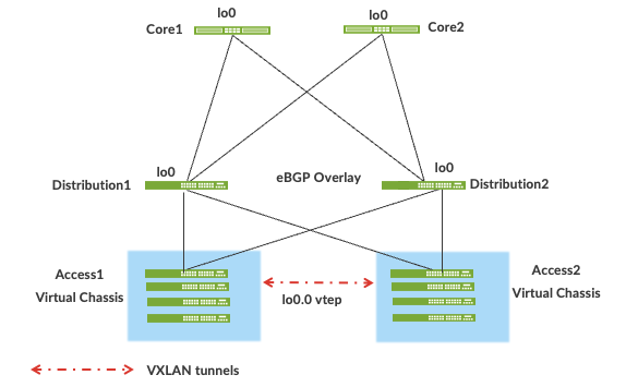
Figure 3. VXLAN VTEP tunnels
VXLAN can be deployed as a tunnelling protocol across a Layer 3 IP Campus Fabric without a control plane protocol. However, the use of VXLAN tunnels alone does not change the flood and learn behavior of the Ethernet protocol.
The two primary methods for using VXLAN without a control plane protocol—static unicast VXLAN tunnels and VXLAN tunnels that are signaled with a multicast underlay—do not solve the inherent flood and learn problem and are difficult to scale in large multitenant environments. These methods are out-of-scope of this documentation.
Understanding EVPN
Ethernet VPN (EVPN) is a BGP extension to distribute endpoint reachability information such as MAC and IP addresses to other BGP peers. This control plane technology uses Multiprotocol BGP (MP-BGP) for MAC and IP address endpoint distribution, where MAC addresses are treated as Type 2 EVPN routes. EVPN enables devices acting as VTEPs to exchange reachability information with each other about their endpoints.
Juniper supported EVPN Standards:
https://www.juniper.net/documentation/us/en/software/junos/evpn-vxlan/topics/concept/evpn.html
What is EVPN-VXLAN:
https://www.juniper.net/us/en/research-topics/what-is-evpn-vxlan.html
The benefits of using EVPNs (Ethernet Virtual Private Network) (Ethernet Virtual Private Network) include:
MAC address mobility
Multitenancy
- Load balancing across multiple links
- Fast convergence
- High Availability
- Scale
- Standards based interoperability
EVPN provides multipath forwarding and redundancy through an all-active model. The access layer can connect to two or more distribution devices and forward traffic using all the links. If an access link or distribution device fails, traffic flows from the access layer toward the distribution layer using the remaining active links. For traffic in the other direction, remote distribution devices update their forwarding tables to send traffic to the remaining active distribution devices connected to the multihomed Ethernet segment.
The technical capabilities of EVPN include:
- Minimal flooding—EVPN creates a control plane that shares end host MAC addresses between VTEPs.
- Multihoming—EVPN supports multihoming for client devices. A control protocol like EVPN that enables synchronization of endpoint addresses between the access switches is needed to support multihoming, because traffic traveling across the topology needs to be intelligently moved across multiple paths.
- Aliasing—EVPN leverages all-active multihoming when connecting devices to the Access layer of a Campus Fabric. The connection off the multihomed Access layer switches is called ESI-LAG, while the devices connect to each Access switch using standard LACP.
- Split horizon—Split horizon prevents the looping of broadcast, unknown unicast, and multicast (BUM) traffic in a network. With split horizon, a packet is never sent back over the same interface it was received on, which prevents loops.
Overlay Network (Data Plane)
VXLAN is the overlay data plane encapsulation protocol that tunnels Ethernet frames between network endpoints over the underlay network. Devices that perform VXLAN encapsulation and decapsulation for the network are referred to as a VXLAN tunnel endpoint (VTEP). Before a VTEP sends a frame into a VXLAN tunnel, it wraps the original frame in a VXLAN header that includes a Virtual Network Identifier (VNI). The VNI maps the packet to the original VLAN at the ingress switch. After applying a VXLAN header, the frame is encapsulated into a UDP/IP packet for transmission to the remote VTEP over the IP fabric, where the VXLAN header is removed and the VNI to VLAN translation happens at the egress switch.
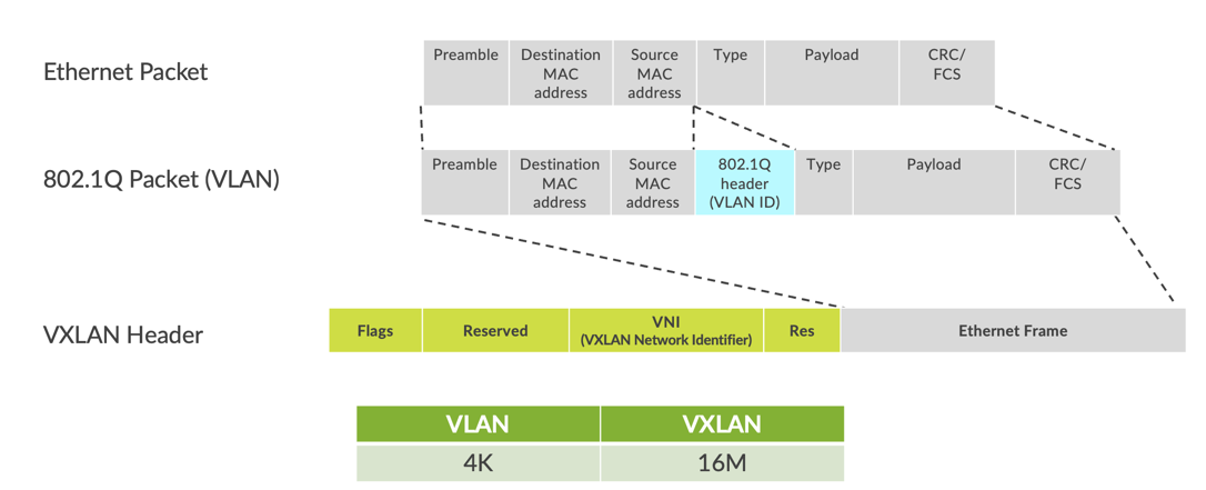
Figure 4: VXLAN Header
VTEPs are software entities tied to the devices’ loopback address that source and terminate VXLAN tunnels. VXLAN tunnels in an IP-Clos fabric are provisioned on the following:
- Access switches to extend services across the Campus Fabric IP Clos
- Core switches, when acting as a Border Router, interconnect the Campus Fabric with the outside network.
- Services Block devices that interconnect the Campus Fabric with the outside network.
Overlay Network (Control Plane)
MP-BGP with EVPN signaling acts as the overlay control plane protocol. Adjacent layer switches set up eBGP peers with each other sourced via loopback addresses while utilizing next hops announced by the underlay BGP sessions. For example, core and distribution devices establish eBGP sessions between each other while the access and distribution devices establish eBGP sessions with each other. When there is a Layer 2 forwarding table update on any switch participating in campus fabric it will send a BGP update message with the new MAC route to other devices in the fabric. Those devices will then update their local evpn database and routing tables.
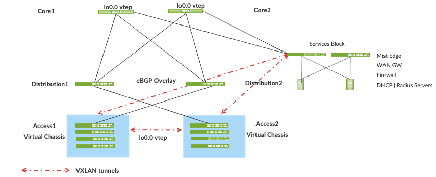
Figure 5: EVPN VXLAN Overlay Network with a Services Block
Resiliency and Load Balancing
Juniper supports BFD, Bi-Directional Forwarding, as part of the BGP protocol implementation. This provides fast convergence in the event of a device or link failure without relying on the routing protocol’s timers. Mist configured BFD minimum intervals of 1000ms and 3000ms in the underlay and overlay respectively. Load Balancing, per packet by default, is supported across all links within the Campus Fabric using ECMP or Equal Cost Multi Pathing enabled at the forwarding plane.
Ethernet Segment Identifier (ESI)
When devices such as servers and access points are multihomed to two or more switches at the Access layer in a Campus Fabric, an ESI-LAG is formed on the Access layer devices. This ESI is a 10-octet integer that identifies the ethernet segment amongst all Access layer switches participating in the ESI. MP-BGP is the control-plane protocol used to coordinate this information. ESI-LAG enables link failover in the event of a bad link, supports active-active load-balancing, and is automatically assigned by Mist.
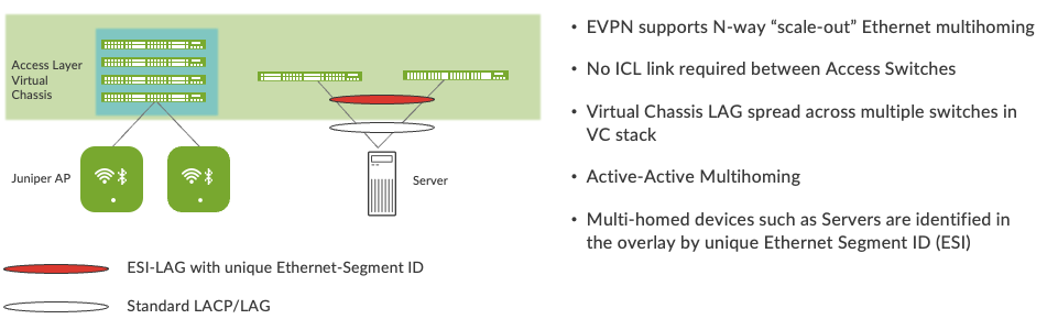
Figure 6. Device resiliency and load balancing
Services Block
Customers may wish to position critical infrastructure services off a dedicated Access Pair of Juniper switches. This could include WAN and Firewall connectivity, Radius and DHCP (Dynamic Host Configuration Protocol) Servers as an example. For those customers who wish to deploy a Lean Core; the dedicated Services Block mitigates the need for the Core to support encapsulation and de-encapsulation of VXLAN tunnels as well as additional capabilities such as Routing Instance and additional L3 (Layer 3) routing protocols. The Services Block Border capability is supported directly off the Core Layer or as a dedicated pair of switches.
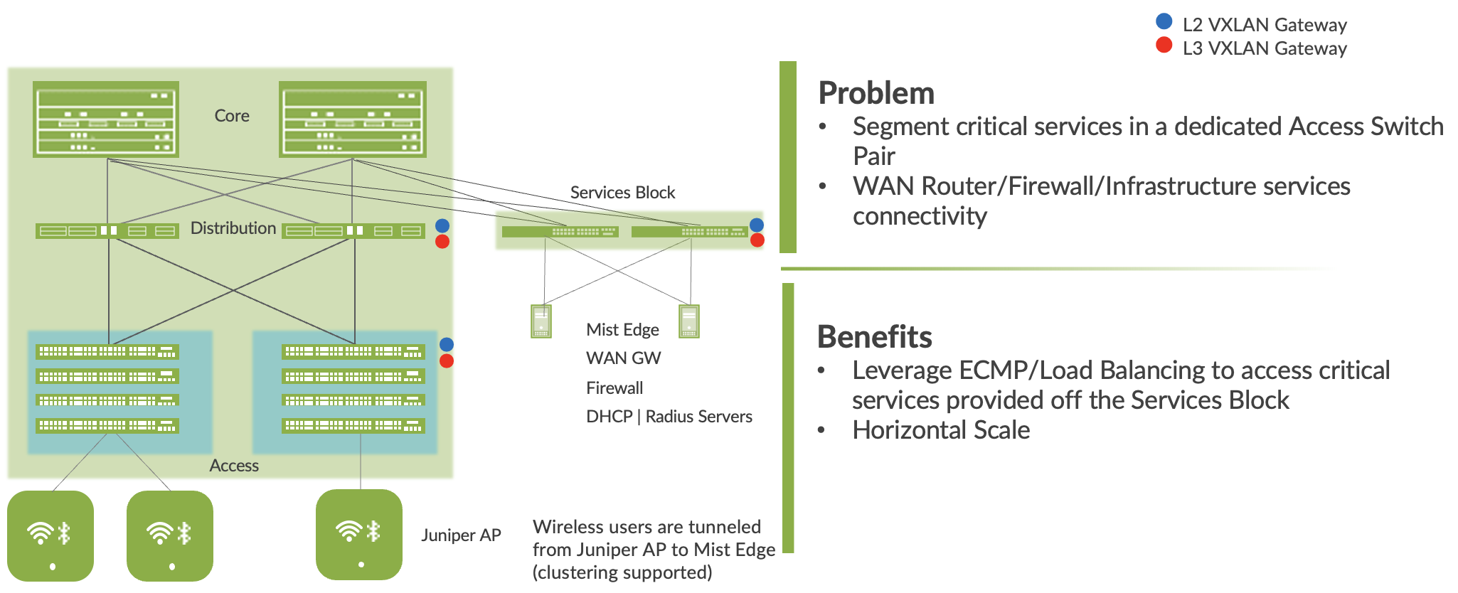
Figure 7. Services Block
Campus Fabric L2 Integration with Enterprise Network
Customers can choose to connect the Campus Fabric to the existing Enterprise Network through the Core layer or dedicated Services Block. L2 integration utilizes ESI-LAG configured through Mist Wired Assurance off the Core or Services Block while the Enterprise Network devices connecting to the Campus Fabric require only LACP interfaces. There is no need to provision an ICL link or to physically connect the Core or Services Block devices. EVPN updates all devices participating in the Ethernet Segment through MP BGP Type4 routes. This process allows all devices participating in the Ethernet Segment (ESI) to nominate a Designated Forwarder and Backup Forwarder to handle BUM to and from the endpoints. ESI-LAG supports active-active load-balancing without the need for loop free avoidance technologies like Spanning Tree.
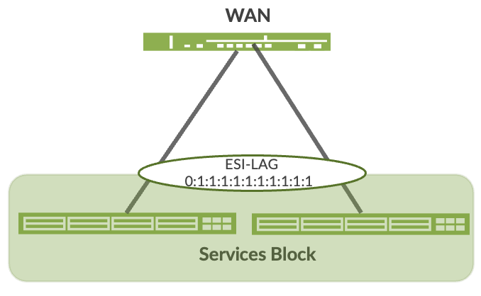
Figure 8. L2 integration via ESI-LAG through the Services Block
Campus Fabric L3 Integration with Enterprise Network
Customers can choose to connect the Campus Fabric to the existing Enterprise Network through the Core layer or dedicated Services Block. L3 integration utilizes standards-based routing protocols like BGP and OSPF to establish peering and neighbor relationships between the Core or Services Block and the Enterprise Network devices.
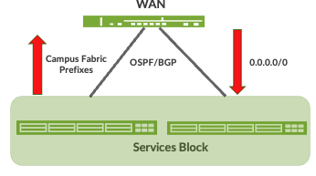
Figure 9. L2 integration via ESI-LAG through the Services Block
Access Layer
The access layer provides network connectivity to end-user devices, such as personal computers, VoIP (Voice over IP) phones, printers, IoT devices, as well as connectivity to wireless access points. EVPN-VXLAN network extends all the way to the access layer switches.
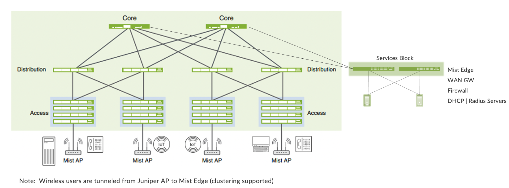
Figure 8. End point access
In this example, each access switch or Virtual Chassis is multihomed to two or more distribution switches. Juniper’s Virtual Chassis reduces the number of ports required on distribution switches and optimizes availability of fiber throughout the campus. The Virtual Chassis is also managed as a single device and supports up to 10 devices (depending on switch model) within a Virtual Chassis.
With EVPN running as the control plane protocol, any access switch or Virtual Chassis device can enable active-active multihoming to the distribution layer. EVPN provides a standards-based multihoming solution that scales horizontally across any number of access layer switches. Please refer to the Scaling section further in this document.
Campus Fabric Organizational Deployment
Mist Campus Fabric supports deployments at the Site and Organizational level. The Organizational deployment shown below, targets Enterprises who wish to align with a POD structure:

Juniper Access points
In our network, we choose Mist Access points as our preferred access point devices. They are designed from the ground up to meet the stringent networking needs of the modern cloud and smart-device era. Mist delivers unique capabilities for both wired and wireless LAN.
- Wired and wireless assurance—Mist is enabled with wired and wireless assurance. Once configured, Service Level Expectations (SLE) for key wired and wireless performance metrics such as throughput, capacity, roaming, and uptime are addressed in the Mist platform. This NCE uses Mist wired assurance services.
- Marvis—An integrated AI engine that provides rapid wired and wireless troubleshooting, trending analysis, anomaly detection, and proactive problem remediation.
Mist Edge
For large campus networks, Mist Edge provides seamless roaming through on-premises tunnel termination of traffic to and from the Juniper Access Points. Juniper Mist Edge extends select microservices to the customer premises while using the Juniper Mist cloud and its distributed software architecture for scalable and resilient operations, management, troubleshooting, and analytics. Juniper Mist Edge is deployed as a standalone appliance with multiple variants for different size deployments.
Evolving IT departments look for a cohesive approach for managing wired, wireless, and wan networks. This full stack approach simplifies and automate operations, provides end-to-end troubleshooting, and evolves into the Self-Driving Network™. The Integration of the Mist platform in this NCE addresses both. For more details on Mist integration and EX switches, see How to Connect Mist Access Points and Juniper EX Series Switches.
Campus Fabric IP Clos Deployment Types
Juniper’s Wired Assurance supports 3 Stage and 5 Stage IP Clos deployments. The 3 Stage IP Clos is targeted towards deployments that do not require a Distribution Layer and have smaller scale requirements. This also allows for cost effective EX4400, EX4650, and QFX5120 switching platforms to be deployed at the Core Layer.
3 Stage Clos
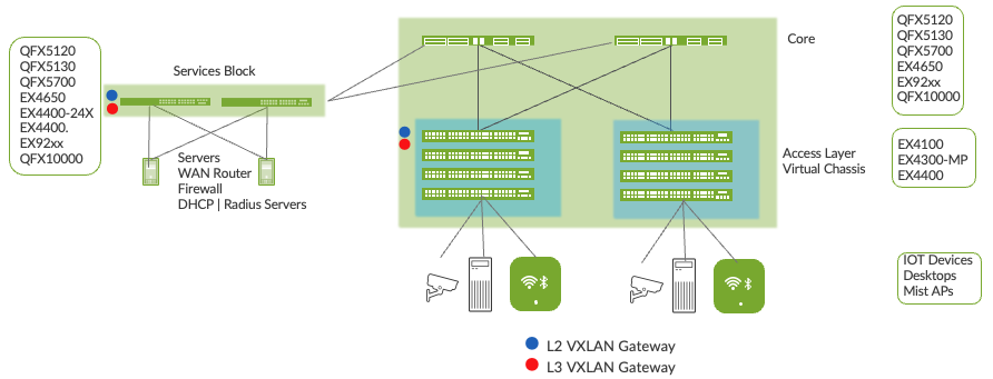
Figure 10. Campus Fabric 3 Stage Clos
5 Stage Clos
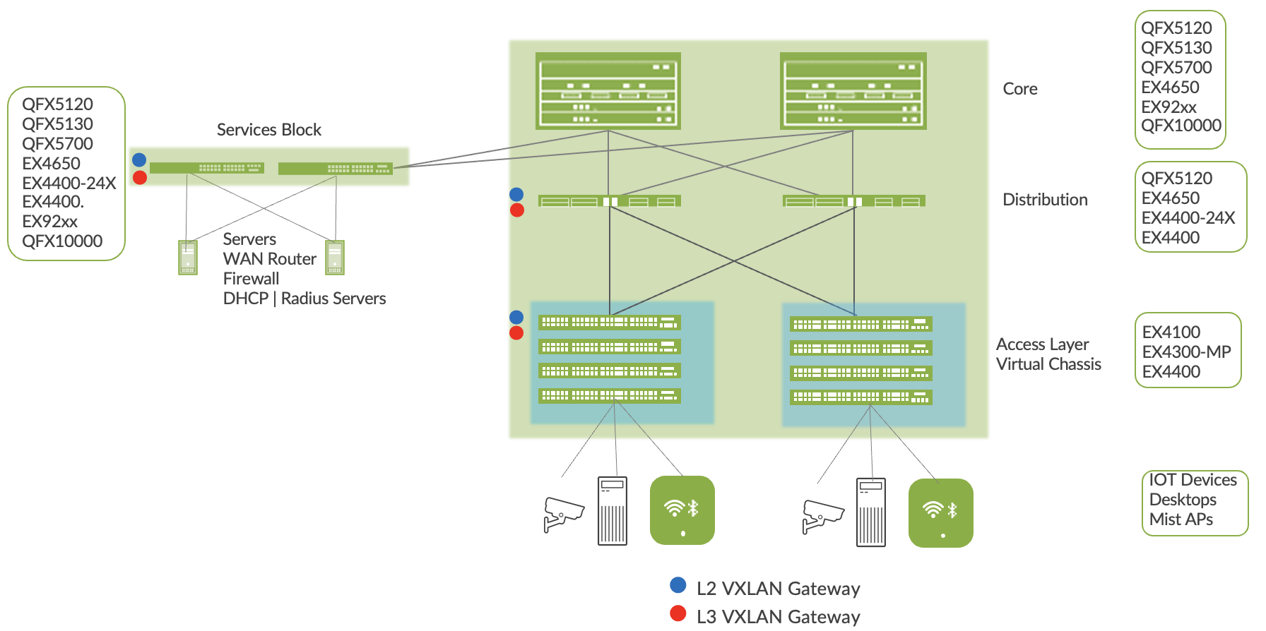
Figure 11. Campus Fabric 5 Stage Clos

Campus Fabric IP Clos Platform Support:
Access Layer:
EX4100
EX4300-MP
EX4400
Distribution Layer:
EX4400/EX4400-24X
EX4650
QFX5120
QFX5130
QFX5700
Core Layer:
EX4650
EX4400-24X
QFX5120
QFX5130
QFX5700
QFX10000
EX92xx
Services Block:
EX4400/EX4400-24X
EX4650
QFX5120
QFX5130
QFX5700
QFX10000
EX92xx
Campus Fabric IP Clos Unicast Scale
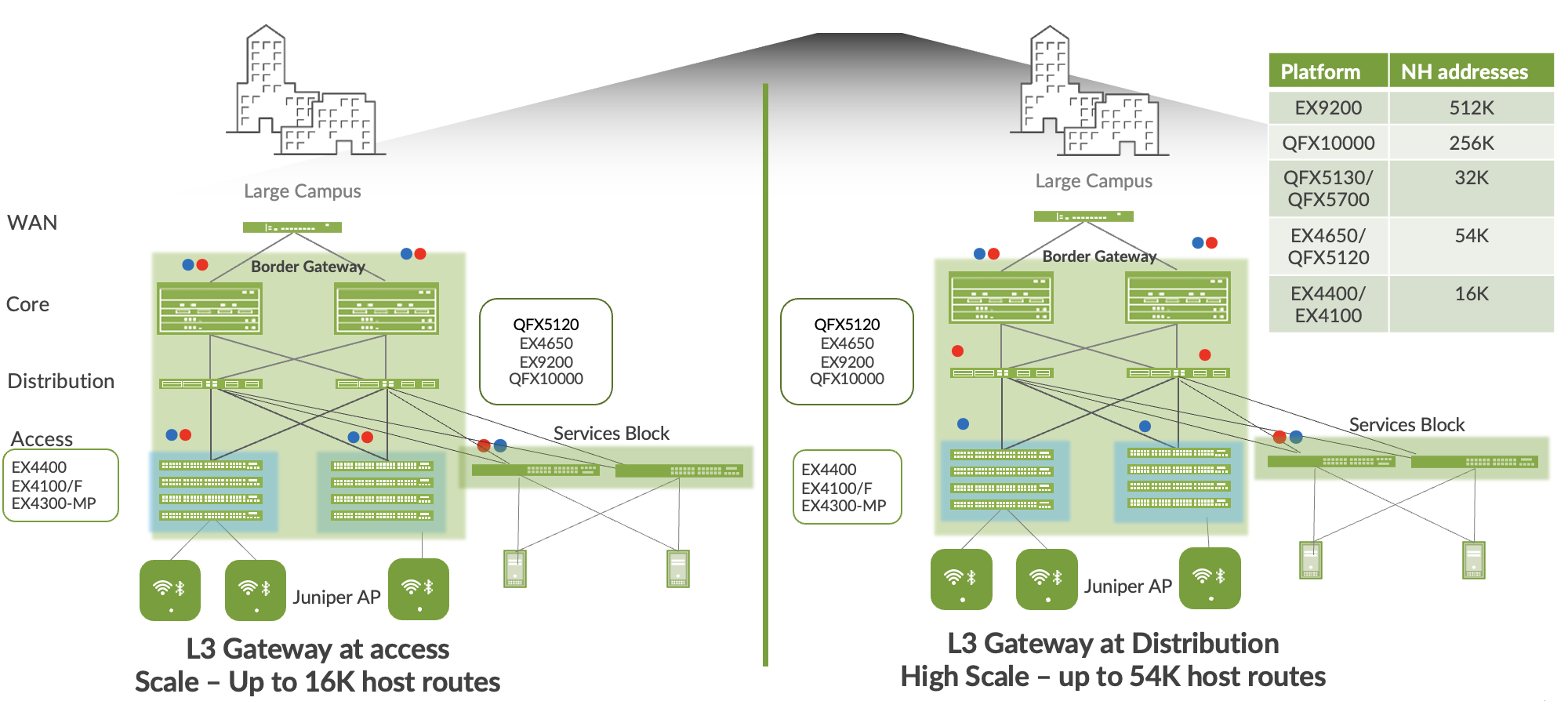
Figure 12. Campus Fabric IP Clos Scale
Juniper Mist Wired Assurance
Mist Wired Assurance is a cloud service that brings automated operations and service levels to the Campus Fabric for switches, IoT devices, access points, servers, printers, etc. It is about simplification every step of the way, starting from Day 0 for seamless onboarding and auto-provisioning through Day 2 and beyond for operations and management. Juniper EX Series Switches provide rich Junos streaming telemetry that enable the insights for switch health metrics and anomaly detection, as well as Mist AI capabilities.
Mist’s AI engine and virtual network assistant, Marvis, further simplifies troubleshooting while streamlining helpdesk operations by monitoring events and recommending actions. Marvis is one step towards the Self-Driving Network™, turning insights into actions and fundamentally transforming IT (Information Technology) operations from reactive troubleshooting to proactive remediation.
Mist Cloud services are 100% programmable using open APIs (Application Programming Interfaces) (Application Programming Interface) for full automation and/or integration with your Operational Support Systems, such as: IT applications, such as Ticketing Systems, IP Management Systems, etc.
Juniper Mist delivers unique capabilities for the WAN (Wide Area Network), LAN (Local Area Network) and Wireless networks
- UI (User Interface) or API (Application Programming Interface) driven configuration at scale
- Service Level Expectations (SLE) for key performance metrics such as throughput, capacity, roaming, and uptime.
- Marvis—An integrated AI engine that provides rapid troubleshooting of Full Stack network issues, trending analysis, anomaly detection, and proactive problem remediation.
- Single Management System
- License Management
- Premium Analytics for long term trending and data storage
To learn more about Juniper Mist Wired Assurance please access the following datasheet: https://www.juniper.net/content/dam/www/assets/datasheets/us/en/cloud-services/juniper-mist-wired-assurance-datasheet.pdf
Campus IP Clos Fabric High Level Architecture
The campus fabric, with an EVPN-VXLAN architecture, decouples the overlay network from the underlay network. This approach addresses the needs of the modern enterprise network by allowing network administrators to create logical Layer 2 networks across one or more Layer 3 networks. In a Campus Fabric deployment, the use of EVPN VXLAN supports native traffic isolation using routing-instances; commonly called VRFs (Virtual Routing and Forwarding) for macro-segmentation purposes.
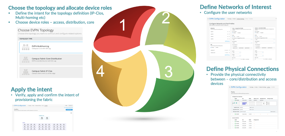
The Mist UI workflow makes it easy to create campus fabrics.
Juniper Mist Wired Assurance
Wired Assurance, through the Mist UI, can be used to centrally manage all Juniper switches. Juniper Mist Wired Assurance gives you full visibility on the devices that comprise your network’s access layer. The Juniper Mist portal provides a user interface to access your architecture through the AI-driven cloud services with your Juniper Mist account. You can monitor, measure, and get alerts on key compliance metrics on the wired network including switch version and PoE (Power Over Ethernet) compliance, switch-AP affinity, and VLAN (Virtual LAN) insights.
Juniper Switch Onboarding to the Mist Cloud:
Wired Assurance, through the Mist UI, is used to build a Campus Fabric IP Clos from ground up. This includes the following:
- Assignment of p2p links between all layers of the Campus Fabric
- Assignment of unique BGP AS numbers per device participating in the underlay and overlay.
- Creation of VRF (Virtual Routing and Forwarding) instances to allow the user the ability to logically segment traffic. This also includes the assignment of new or existing VLANs to each representative VRF
- IP addressing of each L3 (Layer 3) gateway IRB (Integrated Routing and Bridging)
- IP addressing of each lo0.0 loopback
- Configuration of routing policies for underlay and overlay connectivity
- Optimized MTU (Maximum Transmission Unit) settings for p2p underlay, L3 IRB, and ESI-LAG bundles
- Downloadable connection table (.csv format) that can be used by those involved in the physical buildout of the Campus Fabric
- Graphical interface depicting all devices with BGP peering and physical link status
For more information on Juniper Mist Wired Assurance, please leverage the following link: https://www.mist.com/documentation/category/wired-assurance/
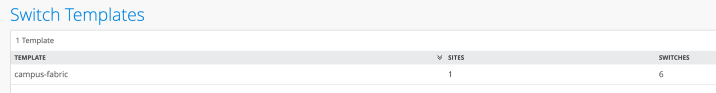
Juniper Mist Wired Assurance Switches Section
The user should validate that each device participating in the Campus Fabric has been adopted or claimed and assigned to a site. The switches were descriptively named to represent the respective layers in the fabric to facilitate building and operating the fabric.
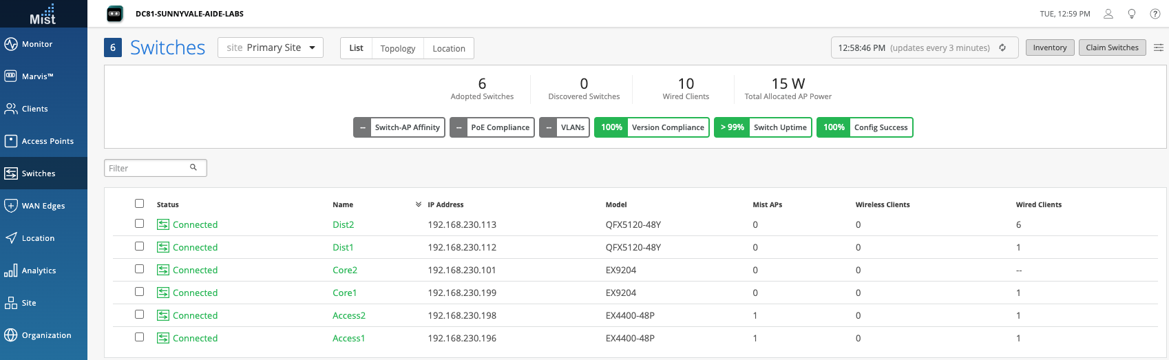
Figure 12. Switch Inventory
Templates
A key feature of switch management through the Juniper Mist cloud is the ability to use templates and a hierarchical model to group the switches and make bulk updates. Templates provide uniformity and convenience, while the hierarchy (Organization, Site, and Switch) provides both scale and granularity.
What templates, and the hierarchical model, means in practice is that you can create a template configuration and then all the devices in each group inherit the template settings. When a conflict occurs, for example when there are settings at both the Site and Organizational levels that apply to the same device, the narrower settings (in this case, Site) override the broader settings defined at the Organization level.
Individual switches, at the bottom of the hierarchy, can inherit all or part of the configuration defined at the Organization level, and again at the Site level. Of course, individual switches can also have their own unique configurations.
You can include individual CLI (Command Line Interface) commands at any level of the hierarchy, which are then appended to all the switches in that group on an “AND” basis– that is, individual CLI settings are appended to the existing configuration (existing setting may replace or appended).
Note: If a user utilizes CLI commands for items not native to the Mist UI, this configuration data will be applied last; overwriting existing configuration data within the same stanza. The CLI Command option can be access from the Switch Template or individual Switch configuration:
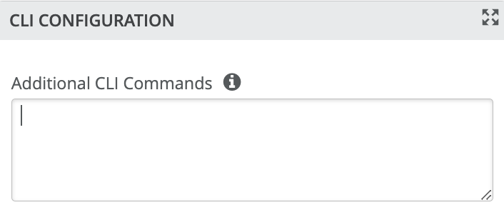
Under Organization and Switch Template:
Topology
Wired Assurance provides the template for LAN and Loopback IP addressing for each device once the device’s management IP address is reachable. Each device is provisioned with a /32 loopback address and /31 point-to-point Interfaces that interconnect adjacent devices within the Campus Fabric IP Clos.
The WAN router can be provisioned via Mist UI but is separate from the campus fabric workflow. The WAN router has a southbound lag configured to connect to the ESI-LAG on the core switches. WAN routers can be standalone or built as an HA (High Availability) cluster.
Create the Campus Fabric
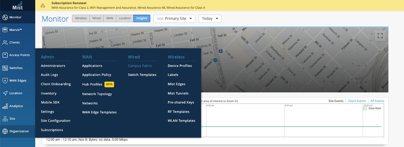
From the Organization option on the left-hand section of the Mist UI, select Wired Campus Fabric
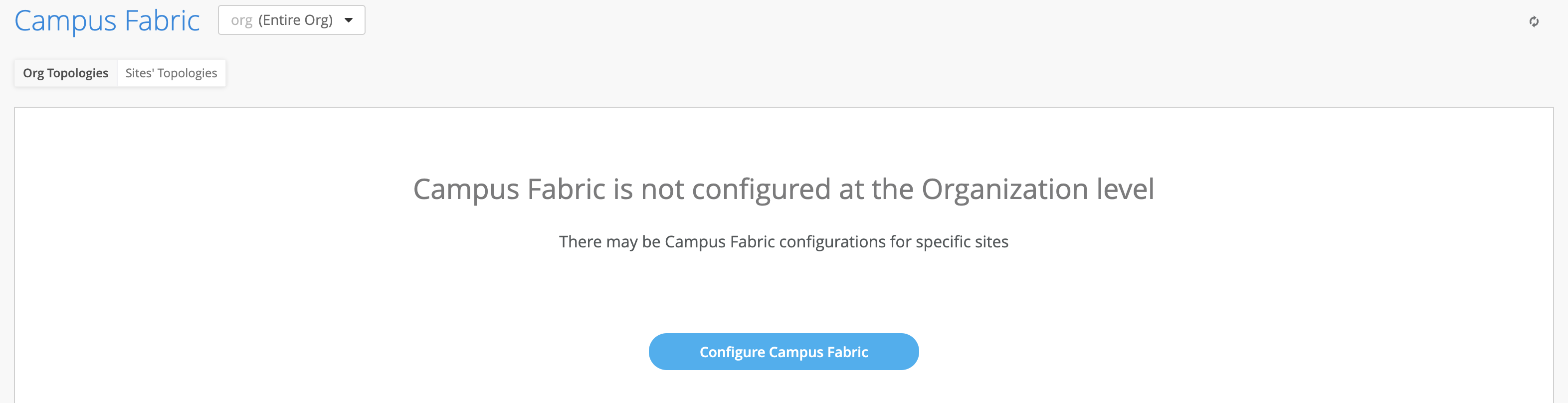
Mist provides the option of deploying a Campus Fabric at the Org or Site level noted on the upper left hand Campus Fabric pull down menu shown below. For example, those who are building a Campus wide architecture with multiple buildings, each building housing distribution and access switches, could consider building an Org level Campus Fabric that ties each of the sites together forming a holistic Campus Fabric. Otherwise, the Site build with a single set of Core, Distribution and Access switches would suffice.
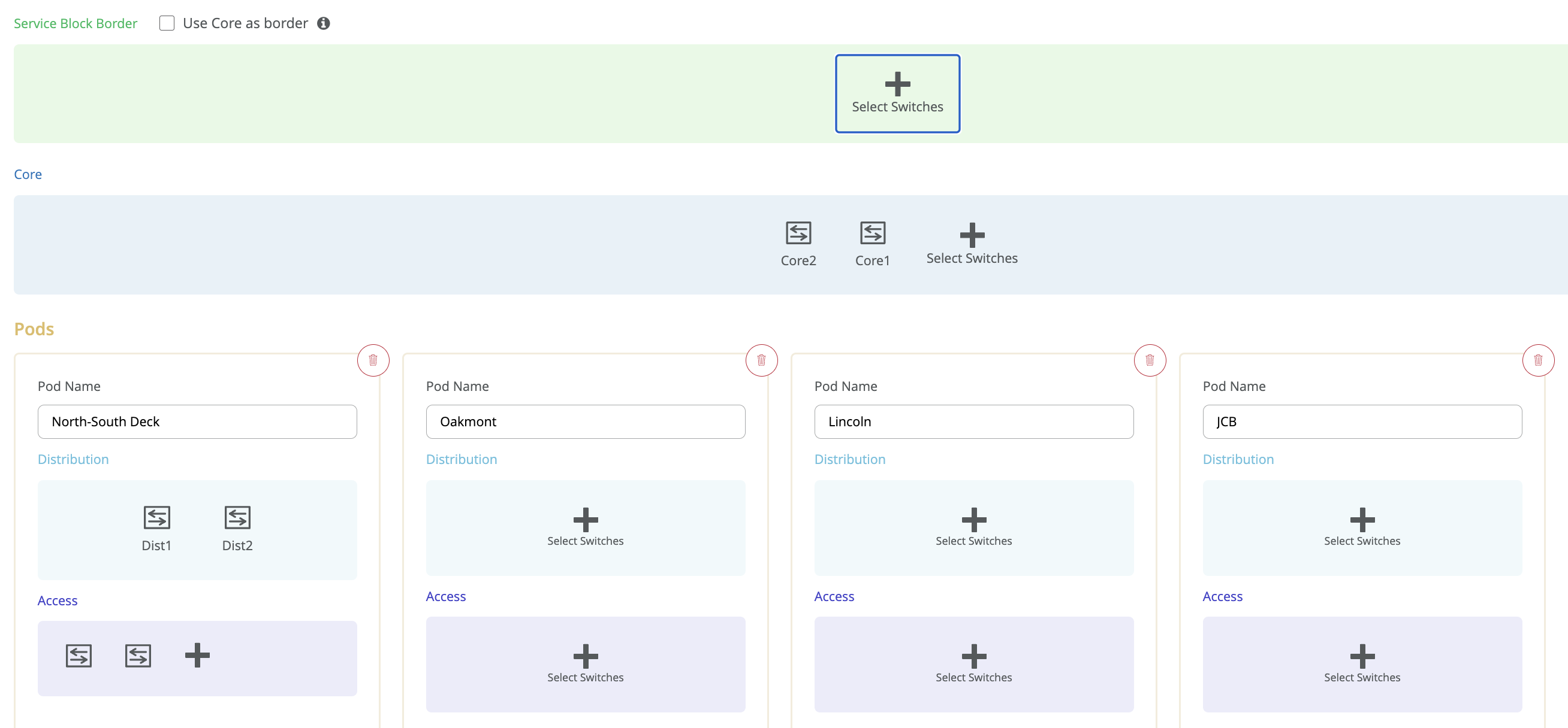
Campus Fabric Org Build
Campus Fabric Site Build
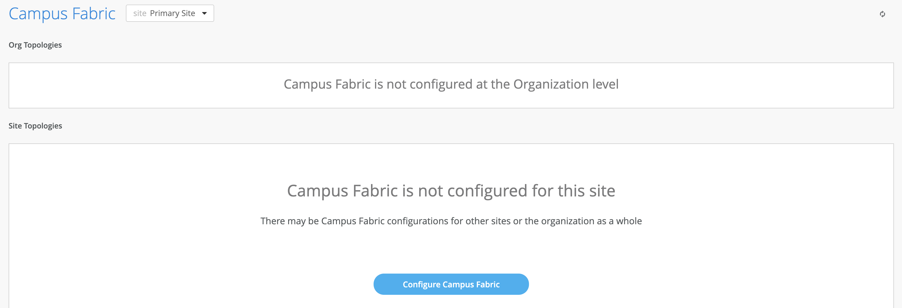

Choose the campus fabric topology
Select the Campus Fabric IP Clos option below: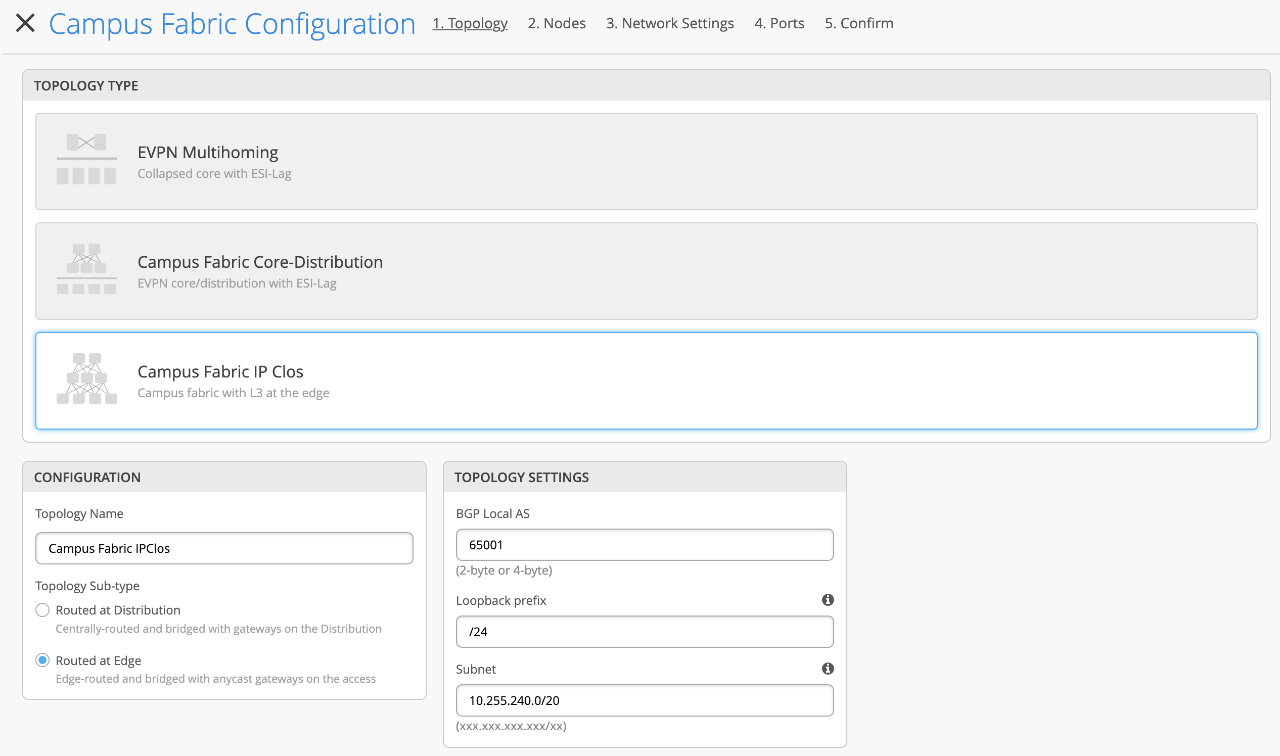
Mist presents the user with the following banner including the estimated time for the Campus Fabric to be built. The process includes the following:
- Mist builds the point-to-point interfaces between all devices with IP addresses chosen from the range presented at the onset of the build.
- Each device is configured with a loopback address from the range presented at the onset of the build.
- eBGP is provisioned at each device with unique BGP autonomous system numbers. The primary goal of the underlay is to leverage ECMP for load balancing traffic on a per packet level for device loopback reachability. The primary goal of the eBGP overlay is support of customer traffic using EVPN-VXLAN.
- IP addressing of each L3 gateway IRB
- IP addressing of each lo0.0 loopback
- Configuration of routing policies for underlay and overlay connectivity
- Optimized MTU settings for p2p underlay, L3 IRB, and ESI-LAG bundles
- VXLAN to VLAN mapping using VNI (Virtual Network Identifier) addresses that are automatically assigned
- VRF creation of corp-it, developers, and guest-wifi and VLAN associated with each VRF
- VXLAN tunnelling creation between Access devices and Access-Core devices (in support of the northbound SRX firewall that will be configured in subsequent steps)
- Downloadable connection table (.csv format) that can be used by those involved in the physical buildout of the Campus Fabric
- Graphical interface depicting all devices with BGP peering and physical link status
Juniper Mist Wired Assurance provides the user with the ability to download a connection table (.csv format) representing the physical layout of the Campus Fabric. This can be used to validate all switch interconnects for those participating in the physical Campus Fabric build. Once the Campus Fabric is built or in the process of being built, the user can download the connection table:
Connection Table spreadsheet:

EVPN Insights
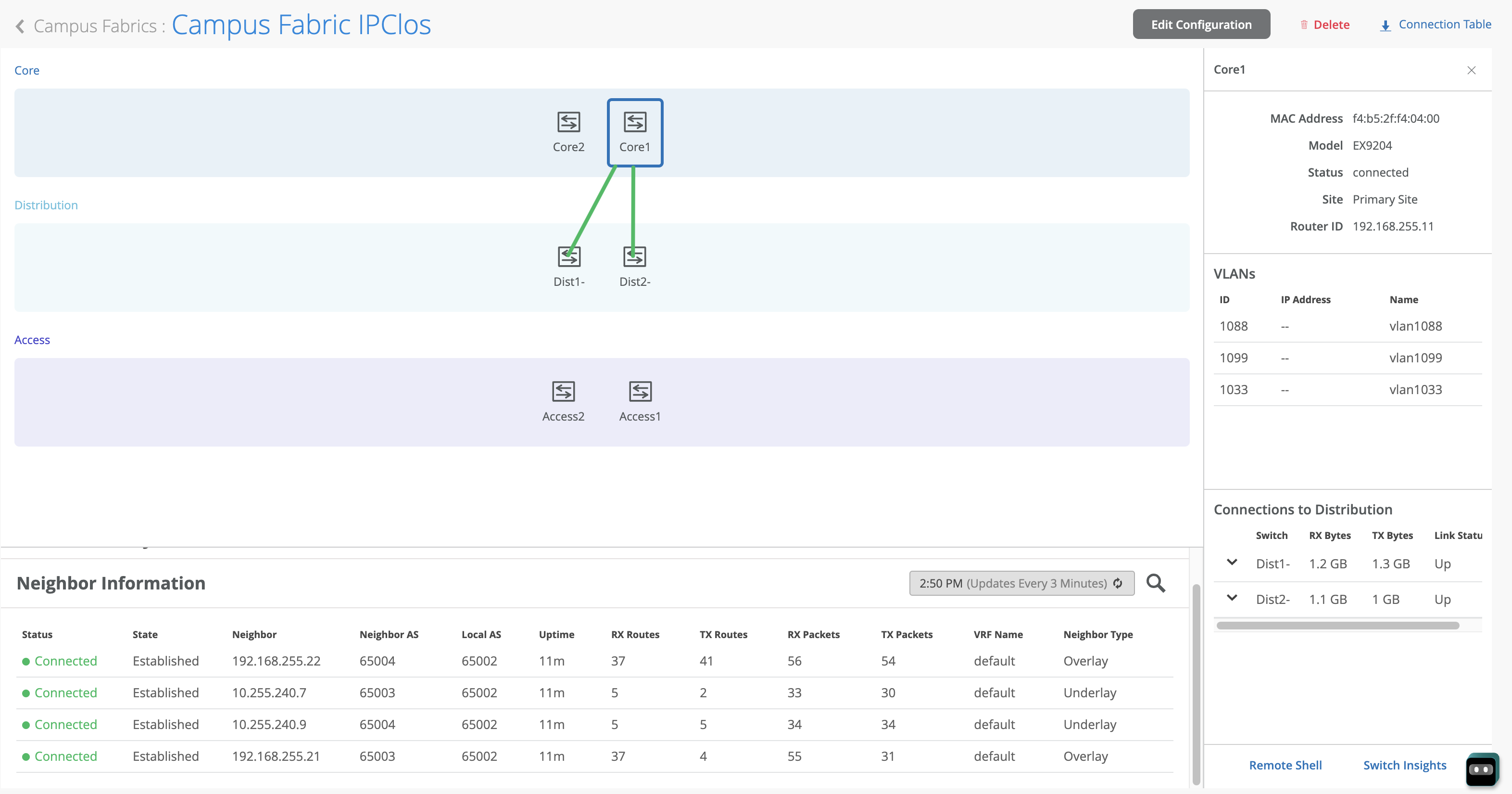
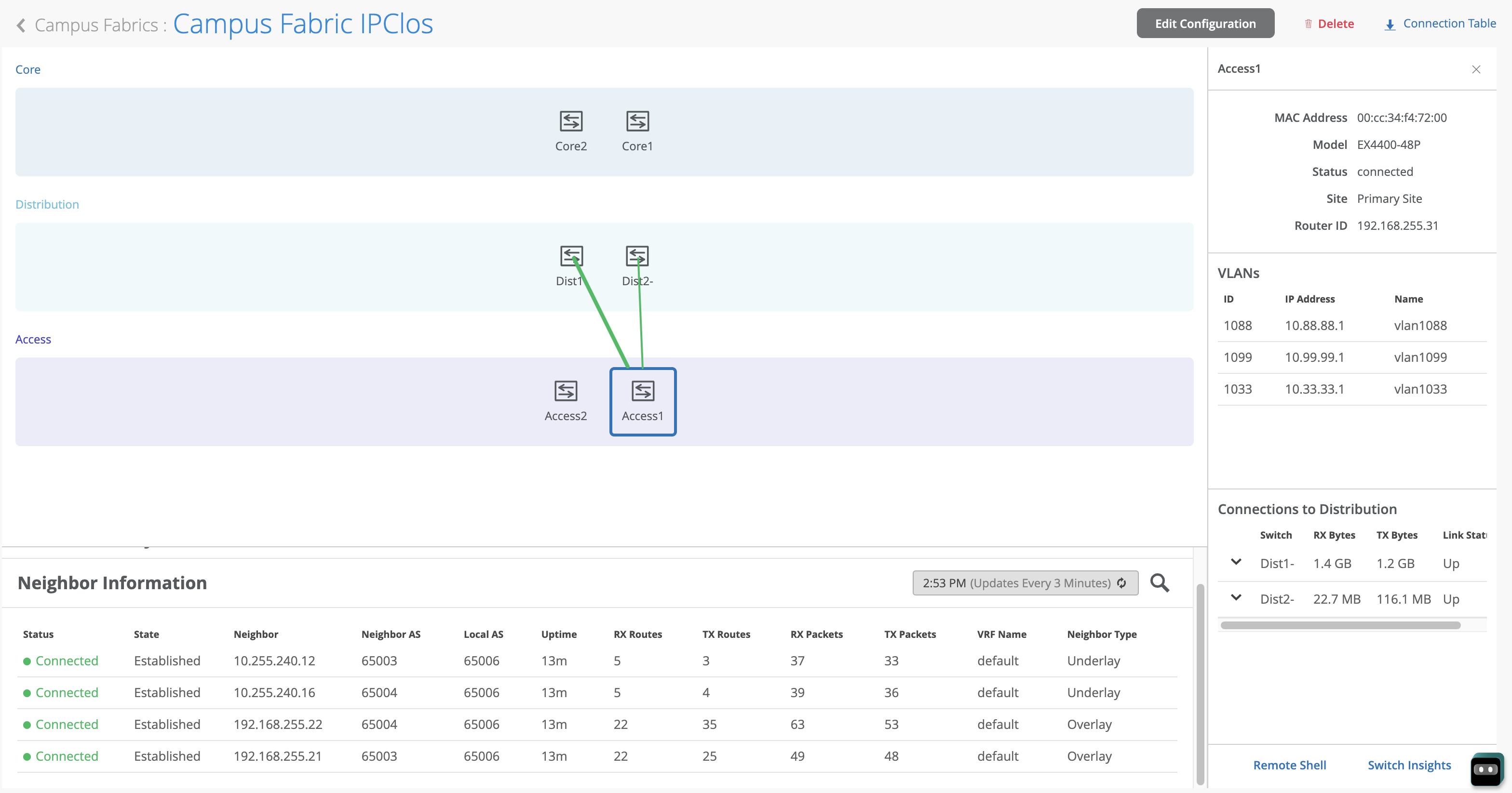
Mist Wired Assurance provides the user with real-time status related to the health of the Campus Fabric IP Clos deployment using telemetry such as BGP neighbor status and TX/RX port statistics. The following screenshots are taken from the Campus Fabric IP Clos build by accessing the Campus Fabric option under the Organization/Wired of the Mist Portal:
From this view, Mist also provides remote accessibility into each device’s console through the Remote Shell option as well as rich telemetry through the Switch Insights option. Remote Shell has been demonstrated throughout this document when displaying real-time operational status of each device during the verification stage.
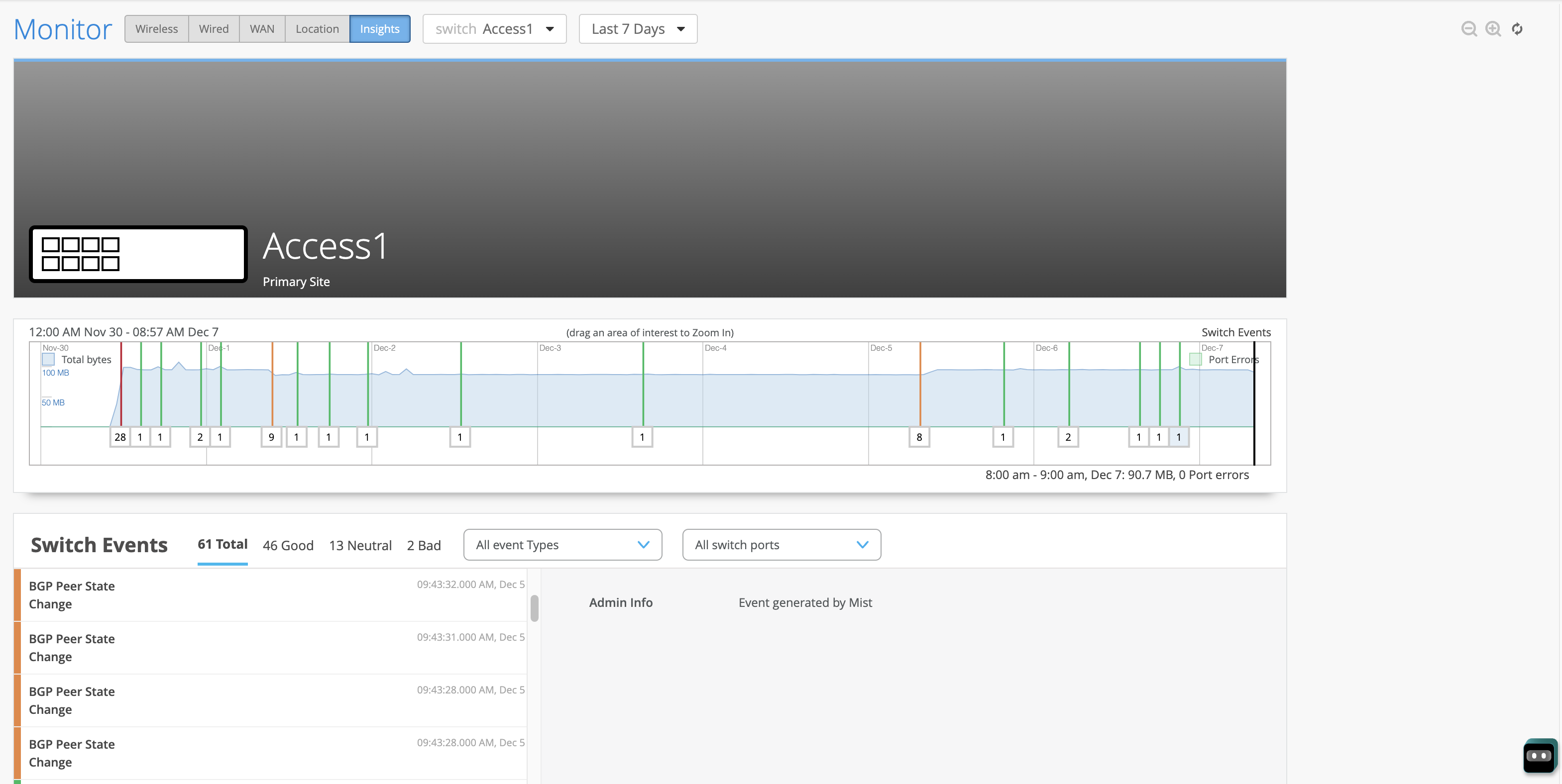
Switch Insights of an Access layer switch displays historical telemetry including BGP peering status critical to the health of the Campus Fabric: