Technology Primer: Campus Fabric Core Distribution ERB
Use Case Overview
Enterprise networks are undergoing massive transitions to accommodate the growing demand for cloud-ready, scalable, and efficient networks, and the plethora of IoT (Internet of Things) and mobile devices. As the number of devices grows, so does network complexity with an ever-greater need for scalability, segmentation, and security. To meet these challenges, you need a network with Automation and AI for operational simplification. Campus Fabric networks provide increased scalability and segmentation using a well-understood standards-based approach EVPN-VXLAN.
Most traditional campus architectures use single-vendor, chassis-based technologies that work well in small, static campuses with few endpoints. However, they are too rigid to support the scalability and changing needs of modern large enterprises.
A Juniper Networks EVPN-VXLAN fabric is a highly scalable architecture that is simple, programmable, and built on a standards-based architecture (https://www.rfc-editor.org/rfc/rfc8365) that is common across campuses and data centers.
The Juniper campus architecture uses a Layer 3 IP-based underlay network and an EVPN-VXLAN overlay network. Broadcast, unknown unicast, and multicast, commonly known as BUM (Broadcast, Unknown unicast, and Multicast) traffic, is handled natively by EVPN and eliminates the need for Spanning Tree Protocols (STP/RSTP). A flexible overlay network based on a VXLAN tunnels combined with an EVPN control plane efficiently provides Layer 3 or Layer 2 connectivity. This architecture decouples the virtual topology from the physical topology, which improves network flexibility and simplifies network management. Endpoints that require Layer 2 adjacency, such as IoT devices, can be placed anywhere in the network and remain connected to the same logical Layer 2 network.
With an EVPN-VXLAN campus architecture, you can easily add core, distribution, and access layer devices as your business grows without having to redesign the network. EVPN-VXLAN is vendor-agnostic, so you can use the existing access layer infrastructure and gradually migrate to access layer switches that support EVPN-VXLAN capabilities once the Core and Distribution part of the network is deployed. Connectivity with legacy switches that do not support EVPN VXLAN is accomplished with standards-based ESI-LAG.
Benefits of Campus Fabric Core Distribution:
With increasing number of devices connecting to the network, you will need to scale your campus network rapidly without adding complexity. Many IoT devices have limited networking capabilities and require Layer 2 adjacency across buildings and campuses. Traditionally, this problem was solved by extending VLANs (virtual LANs) between endpoints using data plane-based flood and learn mechanisms inherent with ethernet switching technologies. The traditional ethernet switching approach is inefficient because it leverages inefficient broadcast and multicast technologies to manage MAC (Media Access Control) addresses. It is also difficult to manage because you need to configure and manually manage VLANs to extend them to new network ports. This problem increases multi-fold when you take into consideration the explosive growth of IoT and mobility.
A campus fabric based on EVPN-VXLAN is a modern and scalable network that uses BGP as the underlay for the core and distribution layer switches. The distribution and core layer switches function as VTEPs (VXLAN Tunnel Endpoint) that encapsulate and decapsulate the VXLAN traffic. In addition, these devices route and bridge packets in and out of VXLAN tunnels.
The Campus Fabric Core Distribution extends the EVPN fabric to connect VLANs across multiple buildings by stretching the Layer 2 VXLAN network with routing occurring in the Core (CRB (Centrally Routed Bridging)) or Distribution (Edge Routed Bridging) layers. This network architecture the core and distribution layers of the topology with integration to access switching via standard LACP (Link Aggregation Control Protocol)
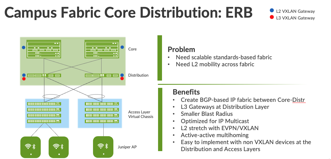
Figure 1 Campus fabric Core Distribution ERB
- A Campus Fabric Core Distribution ERB deployment solves these issues and provides the following benefits:
Reduced flooding and learning—Control plane-based Layer 2/Layer 3 learning reduces the flood and learn issues associated with data plane learning. Learning MAC addresses in the forwarding plane has an adverse impact on network performance as the number of endpoints grows. This is because more management traffic consumes the bandwidth which leaving less bandwidth available for production traffic. The EVPN control plane, deployed at the Core and Distribution layers, handles the exchange and learning of MAC addresses through eBGP routing, rather than a Layer-2 forwarding plane. - Scalability—More efficient control-plane based Layer 2/Layer 3 learning. For example, in a Campus Fabric IP Clos, core switches do not learn the device endpoint addresses, rather they only learn the addresses of the Access layer switches.
- Consistency—A universal EVPN-VXLAN-based architecture across disparate campus and data-center deployments enables a seamless end-to-end network for endpoints and applications.Investment protection – The only requirement to integrate at the access layer is standards based LACP/LAG. This provides investment protection for the section of the network that has the highest cost and footprint.
- Location-agnostic connectivity—The EVPN-VXLAN campus architecture provides a consistent endpoint experience no matter where the endpoint is located. Some endpoints require Layer 2 reachability, such as legacy building security systems or IoT devices. VXLAN overlay provides Layer 2 extension across campuses without any changes to the underlay network. Juniper utilizes optimal BGP timers between the adjacent layers of the Campus Fabric in conjunction with BFD (Bidirectional Forwarding Detection supports fast convergence in the event of a node or link failure) and ECMP (Equal cost multipath). https://www.juniper.net/documentation/us/en/software/junos/sampling-forwarding-monitoring/topics/concept/policy-configuring-per-packet-load-balancing.html
Juniper Mist Wired Assurance
Mist Wired Assurance is a cloud service that brings automated operations and service levels to the Campus Fabric for switches, IoT devices, access points, servers, printers, etc. It is about simplification every step of the way, starting from Day 0 for seamless onboarding and auto-provisioning through Day 2 and beyond for operations and management. Juniper EX Series Switches provide rich Junos streaming telemetry that enable the insights for switch health metrics and anomaly detection, as well as Mist AI capabilities.
Mist’s AI engine and virtual network assistant, Marvis, further simplifies troubleshooting while streamlining helpdesk operations by monitoring events and recommending actions. Marvis is one step towards the Self-Driving Network™, turning insights into actions and fundamentally transforming IT (Information Technology) operations from reactive troubleshooting to proactive remediation.
Mist Cloud services are 100% programmable using open APIs (Application Programming Interfaces) (Application Programming Interface) for full automation and/or integration with your Operational Support Systems, such as: IT applications, such as Ticketing Systems, IP Management Systems, etc.
Juniper Mist delivers unique capabilities for the WAN (Wide Area Network), LAN (Local Area Network) and Wireless networks
- UI (User Interface) or API (Application Programming Interface) driven configuration at scale
- Service Level Expectations (SLE) for key performance metrics such as throughput, capacity, roaming, and uptime.
- Marvis—An integrated AI engine that provides rapid troubleshooting of Full Stack network issues, trending analysis, anomaly detection, and proactive problem remediation.
- Single Management System
- License Management
- remium Analytics for long term trending and data storage
To learn more about Juniper Mist Wired Assurance please access the following datasheet: https://www.juniper.net/content/dam/www/assets/datasheets/us/en/cloud-services/juniper-mist-wired-assurance-datasheet.pdf
Campus Fabric Core Distribution ERB High Level Architecture
The campus fabric, with an EVPN-VXLAN architecture, decouples the overlay network from the underlay network. This approach addresses the needs of the modern enterprise network by allowing network administrators to create logical Layer 2 networks across one or more Layer 3 networks. By configuring different routing instances, you can enforce the separation of virtual networks because each routing instance has its own separate routing and switching table.
The Mist UI workflow makes it easy to create campus fabrics.
Campus Fabric Core Distribution ERB Components
This configuration example uses the following devices:
- Two EX9204 switches as core devices, Software version: Junos OS (Operating System) Release 21.4R1.12 or later
- Two QFX5120 switches as distribution devices, Software version: Junos OS Release 21.4R1.12 or later
- Two Access Layer EX4400 switches, Software version: Junos OS Release 22.1R1.10 or later
- One SRX345 wan router, Software version: 20.2R3-S2.5 or later
- Juniper Access Points
- 2 Linux desktops that act as wired clients
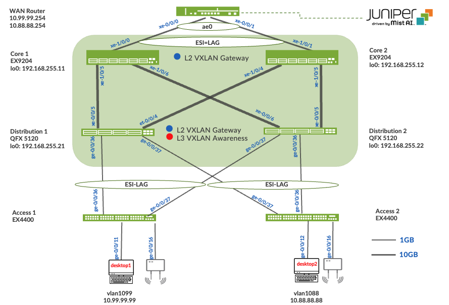
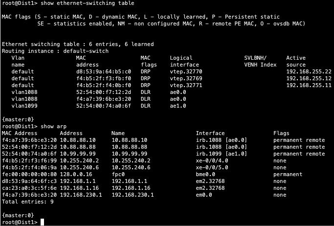
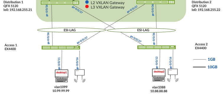
Figure 2. Topology
Juniper Mist Wired Assurance
Wired Assurance, through the Mist UI, can be used to centrally manage all Juniper switches. Juniper Mist Wired Assurance gives you full visibility on the devices that comprise your network’s access layer. The Juniper Mist portal provides a user interface to access your architecture through the AI-driven cloud services with your Juniper Mist account. You can monitor, measure, and get alerts on key compliance metrics on the wired network including switch version and PoE (Power Over Ethernet) compliance, switch-AP affinity, and VLAN insights.
Juniper Switch Onboarding to the Mist Cloud:
Wired Assurance, through the Mist UI, is used to build a Campus Fabric Core Distribution ERB from ground up. This includes the following:
- Assignment of p2p links between the Core and Distribution layers
- Assignment of unique BGP AS numbers per device participating in the underlay and overlay.
- Creation of VRF (Virtual Routing and Forwarding) instances to allow the user the ability to logically segment traffic. This also includes the assignment of new or existing VLANs to each representative VRF
- IP addressing of each L3 gateway IRB (Integrated Routing and Bridging) assigned to the Distribution layer
- IP addressing of each lo0.0 loopback
- Configuration of routing policies for underlay and overlay connectivity
- Optimized MTU (Maximum Transmission Unit) settings for p2p underlay, L3 IRB, and ESI-LAG bundles
- Downloadable connection table (.csv format) that can be used by those involved in the physical buildout of the Campus Fabric
- Graphical interface depicting all devices with BGP peering and physical link status
For more information on Juniper Mist Wired Assurance, please leverage the following link:
https://www.mist.com/documentation/category/wired-assurance/
Juniper Mist Wired Assurance Switches Section
The user should validate that each device participating in the Campus Fabric has been adopted or claimed and assigned to a site. The switches were named for respective layer in the fabric to facilitate building and operating the fabric.
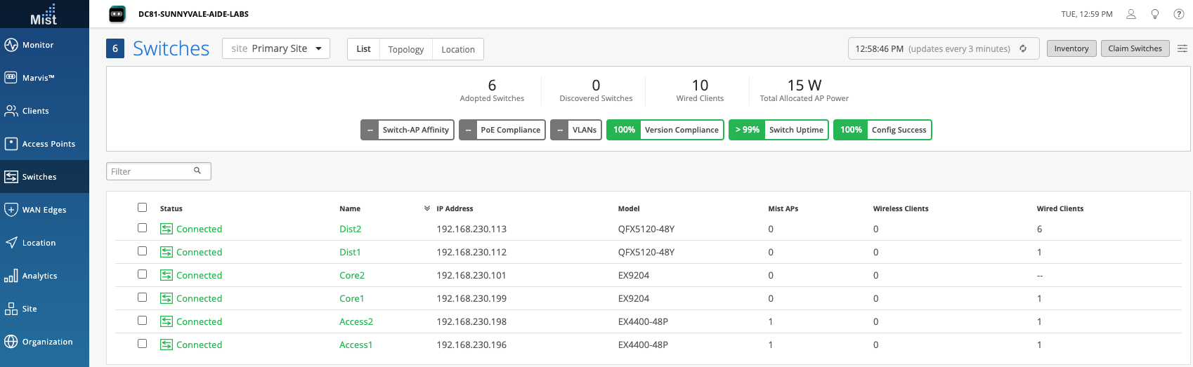
Overview
Templates
A key feature of switch management through the Juniper Mist cloud is the ability to use configuration templates and a hierarchical model to group the switches and make bulk updates. Templates provide uniformity and convenience, while the hierarchy (Site and Switch) provides both scale and granularity.
What templates, and the hierarchical model, means in practice is that you can create a template configuration and then all the devices in each group inherit the template settings. When a conflict occurs, for example when there are settings at both the Site and Organizational levels that apply to the same device, the narrower settings (in this case, Site) override the broader settings defined at the Organization level
Individual switches, at the bottom of the hierarchy, can inherit all or part of the configuration defined at the Organization level, and again at the Site level. Of course, individual switches can also have their own unique configurations.
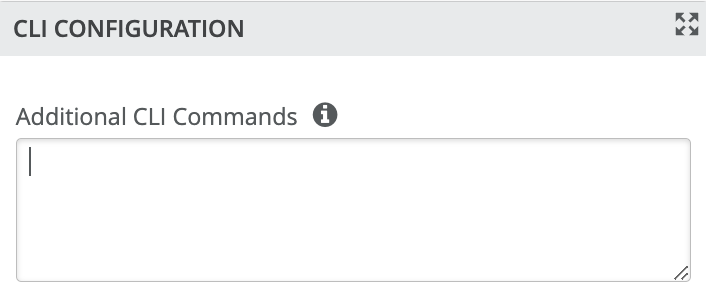
You can include individual CLI (Command Line Interface) commands at any level of the hierarchy, which are then appended to all the switches in that group on an “AND” basis– that is, individual CLI settings are appended to the existing configuration (existing setting may replace or appended).
Note: If a user utilizes CLI commands for items not native to the Mist UI, this configuration data will be applied last; overwriting existing configuration data within the same stanza. The CLI Command option can be access from the Switch Template or individual Switch configuration:
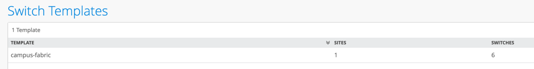
Under Organization and Switch Templates, we utilize the following template
Topology
Wired Assurance provides the template for LAN and Loopback IP addressing for each Core and Distribution device once the device’s management IP address is reachable. Each device is provisioned with a /32 loopback address and /31 point-to-point interfaces that interconnect Core and Distribution devices within the Campus Fabric Core Distribution. The devices such as the Access Layer of switches connect to the Distribution layer using standard LAG (Link Aggregation Groups); while the Distribution utilizes ESI-LAG in a multihoming, load balancing manner.
The WAN router can be provisioned via Mist UI but is separate from the campus fabric workflow. The WAN router has a southbound lag configured to connect to the ESI-LAG on the core switches. WAN router can standalone or built as an HA (High Availability) cluster. In this document, a single SRX firewall is used as the WAN router.
Create the Campus Fabric
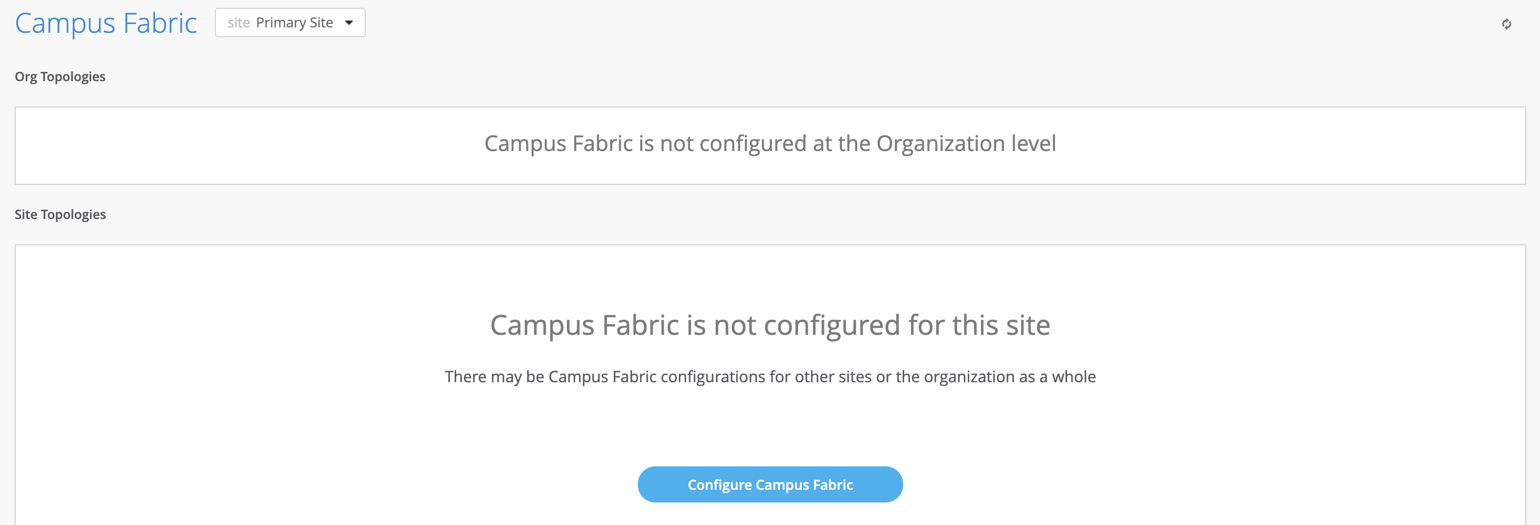
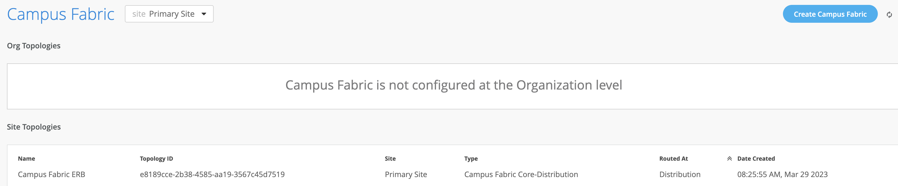
From the Organization option on the leaf hand section of the Mist UI, select Wired Campus Fabric
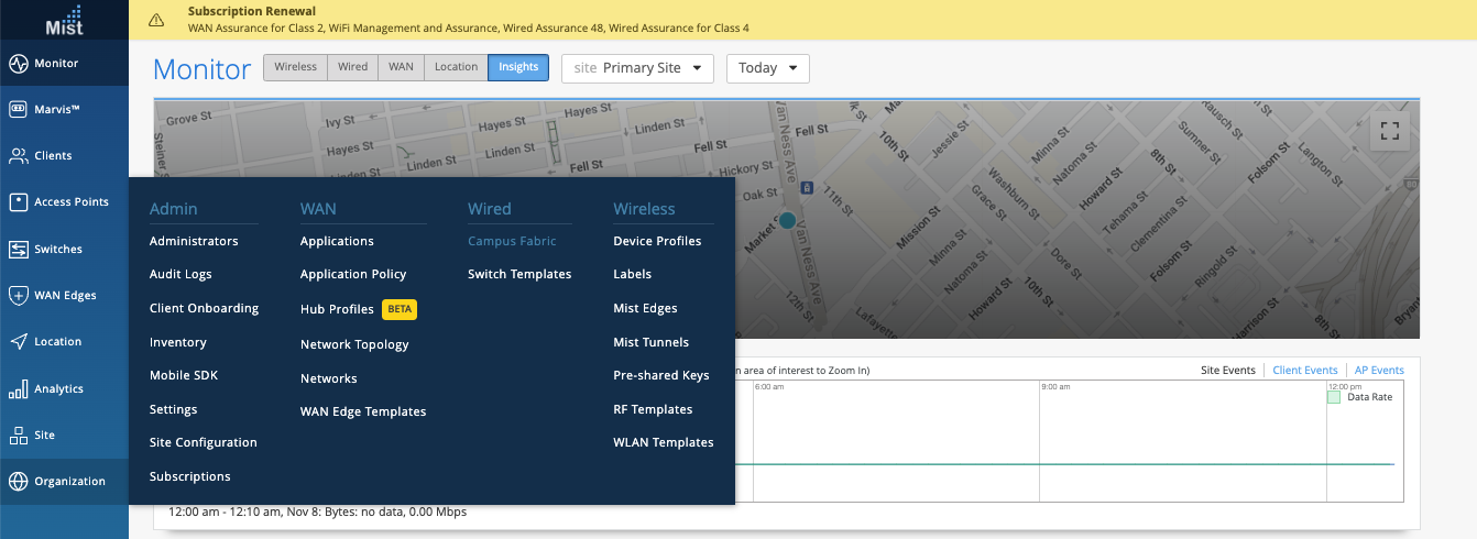
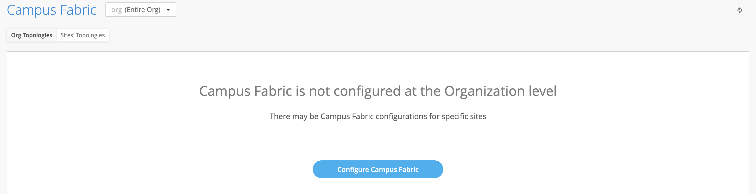
Mist provides the option of deploying a Campus Fabric at the Org or Site level noted on the upper left hand Campus Fabric pull down menu shown below. For example, those who are building a Campus wide architecture with multiple buildings, each building housing distribution and access switches, could consider building an Org level Campus Fabric that ties each of the sites together forming a holistic Campus Fabric. Otherwise, the Site build with a single set of Core, Distribution and Access switches would suffice.
Campus Fabric Org Build
Campus Fabric Site Build

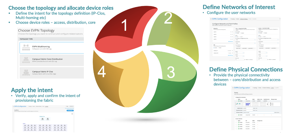
Choose the campus fabric topology
Select the Campus Fabric Core-Distribution
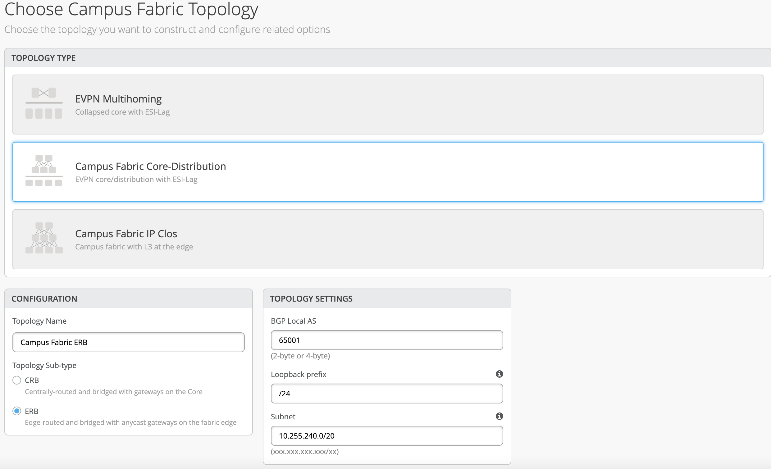
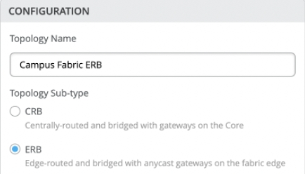
Mist provides a section to name the Campus Fabric Core Distribution ERB.
Configuration
- Provide a name in accordance with company standards
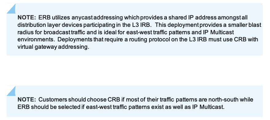
Topology Sub-type
- CRB
- ERB
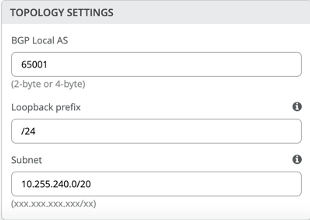
Topology Settings
- BGP Local AS: represents the starting point of private BGP AS numbers that will automatically be allocated per device. The user can use whatever private BGP AS number range suits their deployment, routing policy will be provisioned by Mist to ensure the AS numbers are never advertised outside of the fabric.
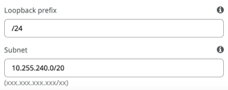
- Loopback prefix: represents the range of IP addresses associated with each device’s loopback address. The user can use whatever range suits their deployment. VXAN tunnelling using a VTEP is associated with this address.
- Subnet: represents the range of IP addresses utilized for point-to-point links between devices. L The user can use whatever range suits their deployment. Mist breaks this subnet into /31 subnet addressing per link. This number can be modified to suit the specific deployment scale. For example, /24 would provide up to 128 p2p /31 subnets.

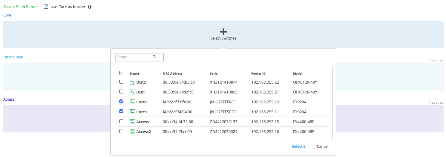
Select campus fabric nodes
The user selects devices to participate at each Layer of the Campus Fabric Core Distribution ERB. Juniper recommends the user validate each device’s presence in the site switch inventory prior to the creation of the Campus Fabric.
The next step is to assign the switches to the layers. Since the switches were named relative to target layer functionality, they can be quickly assigned to their roles.
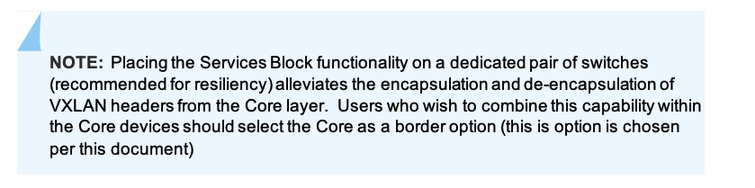
Services Block Router is where the Campus Fabric would interconnect external devices such as firewalls, routers, or critical devices such as DHCP and Radius servers (as an example). Devices to which external services connect to the Campus Fabric are known as Border Leafs. If the user wishes to connect these services/devices to the Campus Fabric Core Distribution ERB in a separate device or pair of devices, the Use Core as border option should be unchecked and the devices chosen by choosing the Select Switches option.
Once all layers have selected the appropriate devices, the user must provide a loopback IP address for each device. This loopback is associated with a logical construct called a VTEP; used to source the VXLAN Tunnel. Campus Fabric Core Distribution ERB has VTEPs for VXLAN tunnelling on the Distribution switches and the Core switches when enabling the Core Border option.
The loopback addresses and router-ids should be the in same address space. The router-id of the loopback can be customized to differentiate between core, distribution, and access. This can help identify devices if you are troubleshooting or following next hops. The loopback is also used as the router-id and will be used for overlay eBGP peering and VXLAN tunnel termination.
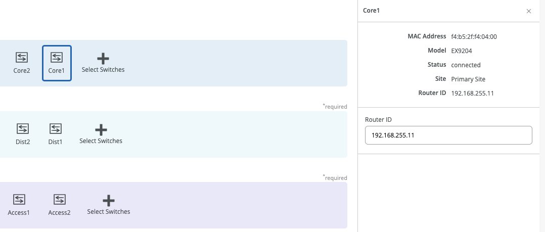

The loopback prefix is used for import /export policies. The subnet addresses are used for point-to-point links throughout the Fabric. Mist automatically creates policies that import, and export loopback addresses used within the Campus Fabric. The selection of fabric type presents the user with default settings, which can be adapted as required.
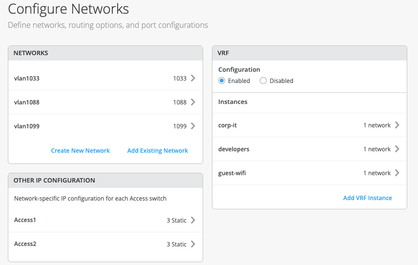
Configure Networks
Mist presents the user with input for Network information such as VLANs and VRF (routing instances for traffic isolation purposes) options. VLANs are mapped to VNIs (Virtual Network Identifier) and can optionally be mapped to VRFs (Virtual Routing and Forwarding) to provide customers a way to logically separate traffic patterns such as IoT devices from Corp IT.
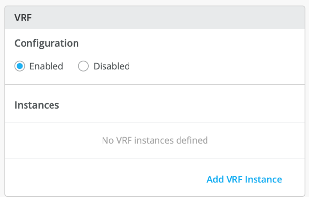
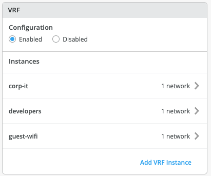
VRF
In a Campus Fabric deployment, the use of EVPN VXLAN supports native traffic isolation using routing-instances; commonly called VRFs for macro-segmentation purposes.
Routing Instance Overview:
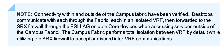
VLANs can be placed into a common VRF where all VLANs within each VRF have full connectivity amongst themselves and other external networking resources. A common use case is the isolation of Guest Wi-Fi traffic from most Enterprise domains save Internet connectivity. By default, the Campus Fabric provides complete isolation between VRFs forcing inter-VRF communications to traverse a Firewall or security compliance. This aligns with most Enterprise security use-cases and compliance and is represented in this document.

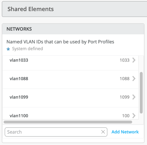
Networks
VLANs can be created or imported under this section including the IP subnet and Default GW per each VLAN.
The Shared Elements section of the campus-fabric template includes the Networks section mentioned above where VLANs are created.
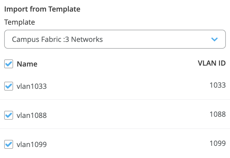
Back to the Campus Fabric build, the user selects the existing template that includes L2 VLAN information. All VLAN and IP information will be inherited from the template
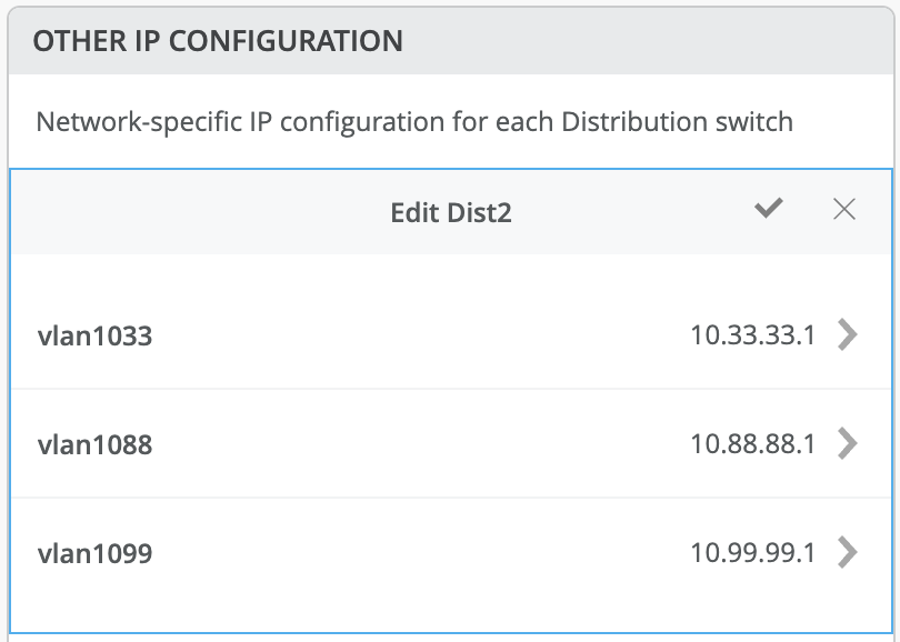
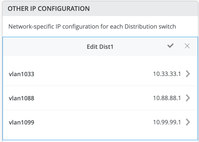
Other IP Configuration
Mist Wired Assurance provides automatic IP addressing (IRBs) for each of the VLANs. Port Profiles and Port Configuration then associate the VLAN with specified ports. In this case, we selected Campus Fabric ERB at the onset of the Campus Fabric build.
This option utilizes anycast addressing for all devices participating in the L3 subnet. In this case, Dist1 and Dist2 switches will be configured with the same IP address for each L3 subnet.
More on Anycast Gateways can be found here:
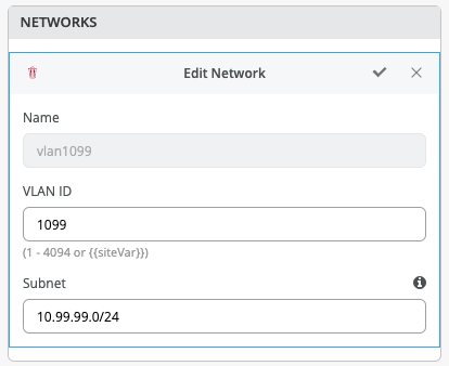
By default, all VLANs are placed in the default VRF. The VRF option allows the user to group common VLANs into the same VRF or separate VRFs depending on traffic isolation requirements. This example includes 3 VRFs or routing instances: corp-it | developers | guest-wifi. Here, the user builds the first corp-it VRF and selects the pre-defined vlan 1099.
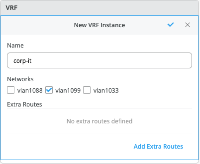
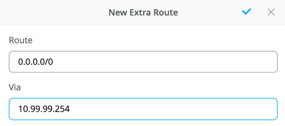
By default, inter-VRF communications is not supported within the Campus Fabric. If inter-VRF communications is required, each VRF can include extra routes such as a Default Route that will instruct the Campus Fabric to use an external router or firewall for further security inspection or routing capabilities. In this example, all traffic is trunked over the ESI-LAG and the Juniper SRX handles inter-VRF routing. Figure 2. Topology
Notice the SRX participates in the VLANs defined within the Campus Fabric and is the gateway of last resort for all traffic leaving the subnet. The user selects the “Add Extra Routes” option to inform Mist to forward all traffic leaving 10.99.99.0/24 to utilize the next hop of the Juniper SRX firewall: 10.99.99.254
The user creates 2 additional VRFs
- developers using vlan 1088 with 0.0.0.0/0 utilizing 10.88.88.254
- guest-wifi using vlan 1033 with 0.0.0.0/0 utilizing 10.33.33.254
 The final step in the Configure Networks section is the Distribution/Access Port Configuration:
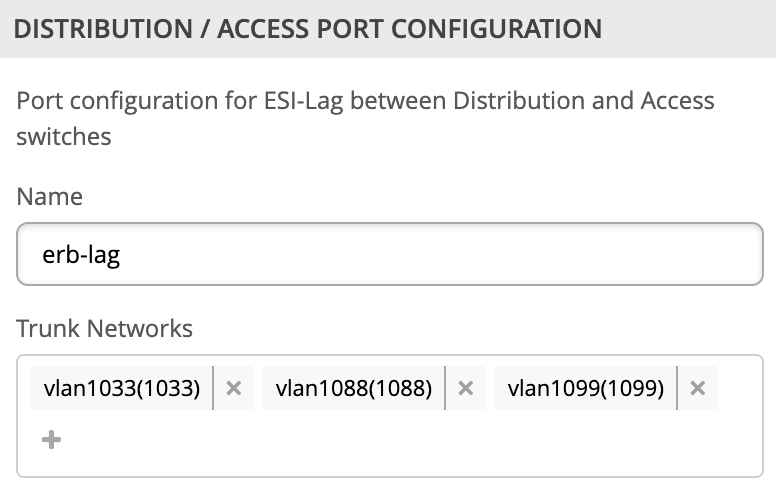
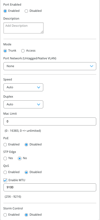
The section configures the active-active ESI-LAG trunks between Distribution and Access switches. Here, we name the port configuration and include VLANs associated with this configuration. The advanced tab provides additional configuration options:
Now that all VLANs are configured and assigned to each VRF, and the Distribution/Access ESI-LAGs have been built, the user can move to the next step by clicking the Continue button at the upper right section of the Mist UI.
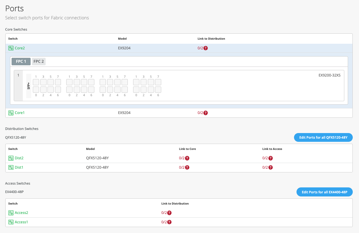
Configure campus fabric ports
The final step is the selection of physical ports between Core, Distribution and Access Switches.
Note: Juniper recommends the user have the output of the show lldp neighbors command from each switch (assuming LLDP (Link Layer Discovery Protocol) is enabled before the switches were selected). This output provides a source of truth for which ports should be selected during at each layer.
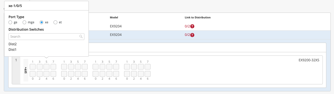
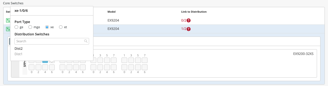
Core Switches
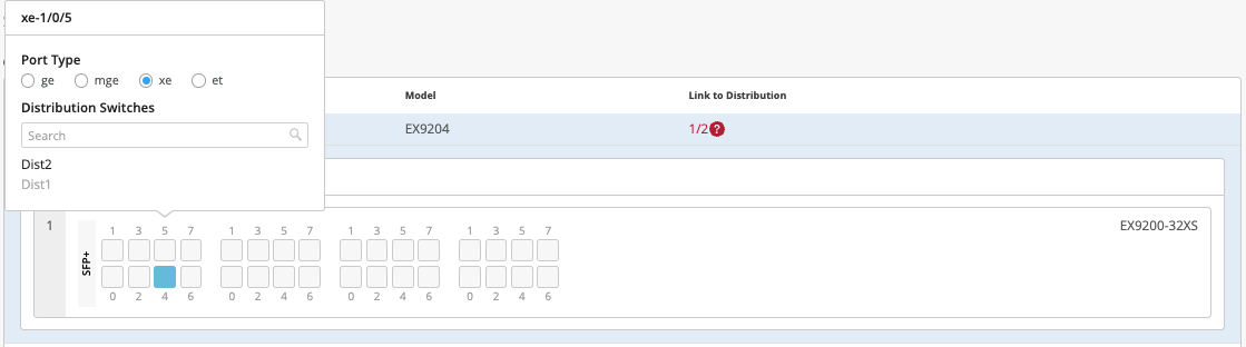
Core1:
Starting with Core1, the user selects xe-1/0/5 and xe-1/0/6 terminating on Distribution Switches 1 and 2 respectively.
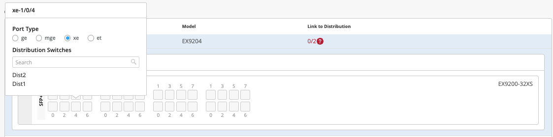
Core2:
On Core2, the user selects xe-1/0/4 and xe-1/0/5 terminating on Distribution Switches 1 and 2 respectively:
Distribution Switches
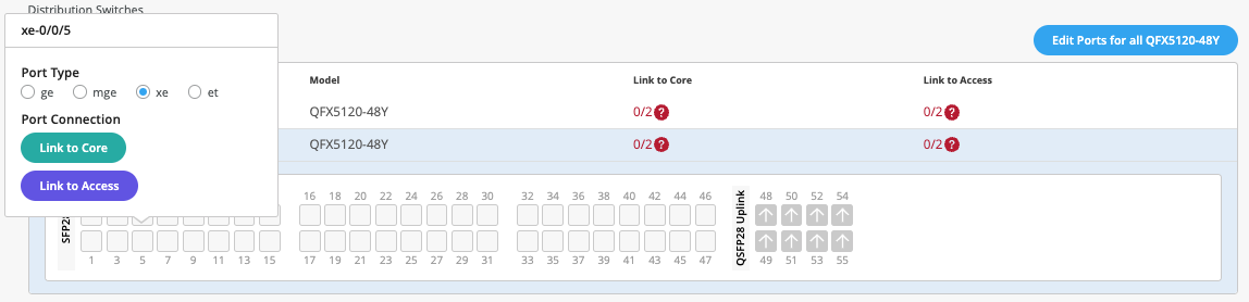
Now moving on to the Distribution Switches, you will notice 2 interconnect options exist
- Link to Core
- Link to Access
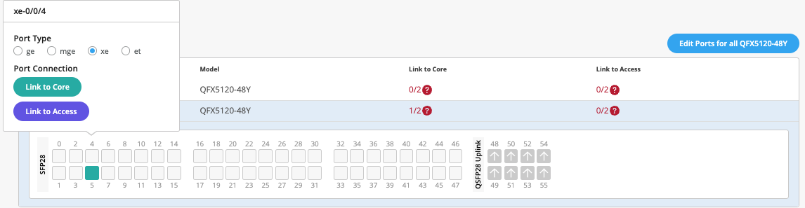
Dist1:
The user selects Link to Core and choose xe-0/0/5 and xe-0/0/4 terminating on Core Switches 1 and 2 respectively.
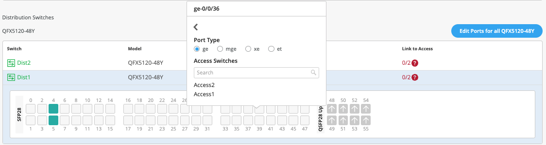
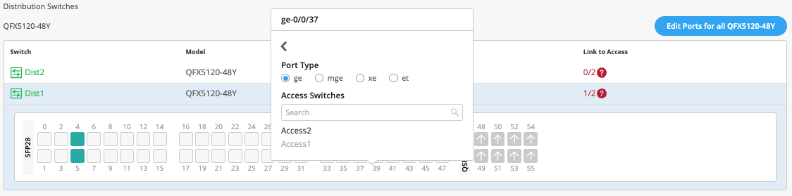
The user selects Link to Access and choose ge-0/0/36 and ge-0/0/37 terminating on Access Switches 1 and 2 respectively:
Next, the user selects the following interconnects off Dist2:
- Link to Core
- xe-0/0/6 – Core1
- xe-0/0/5 – Core2
- Link to Access
- ge-0/0/36 – Access2
- ge-0/0/37 – Access1
Access Switches
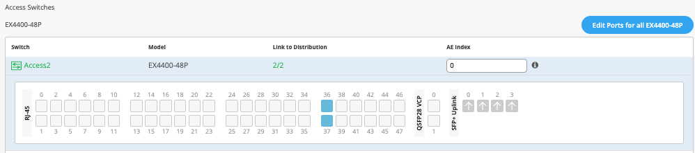
The user only needs to know which interfaces will be used to interconnect with the Distribution switch but does not need to know the specific mapping. The system bundles all interfaces into a single ethernet bundle through the AE (Aggregate Ethernet) Index option. This greatly simplifies the physical port build for each access switch
Access1/2:
The user selects both uplinks and interface speed, while allowing Mist to define each AE index. In this case, uplinks ge-0/0/36/37 are selected as Links to Distribution on both Access switches and AE Index 0/1 (system default numbering) on Access1/2 respectively.

Once the user has completed selecting all requisite port combinations, they will select the Continue button at the upper right-hand corner of the Mist UI.
Campus Fabric Configuration Confirmation
This last section provides the user with the ability to confirm each device’s configuration as shown below:

Once the user has completed verification, they will select the Apply Changes option at the upper right-hand corner of the Mist UI
![]()
The user is presented a second stage confirmation, confirm to create the fabric.
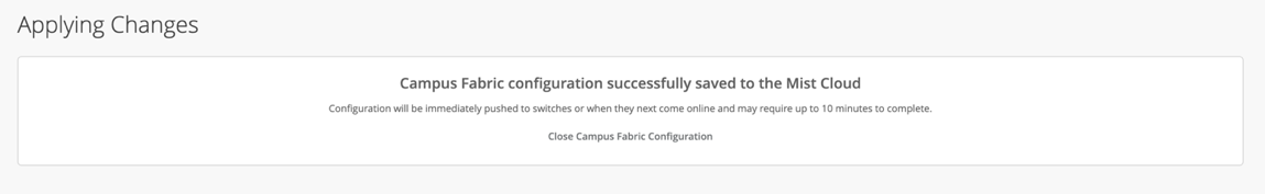
Mist presents the user with the following banner including the estimated time for the Campus Fabric to be built. The process includes the following:
- Mist builds the point-to-point interfaces between Distribution and Core devices with IP addresses chosen from the range presented at the onset of the build.
- Each device is configured with a loopback address from the range presented at the onset of the build.
- eBGP is provisioned at each device with unique BGP autonomous system numbers. The primary goal of the underlay is to leverage ECMP for load balancing traffic on a per packet level for device loopback reachability. The primary goal of the eBGP overlay is support of customer traffic using EVPN-VXLAN.
- IP addressing of each L3 gateway IRB located on Dist1 and Dist2
- IP addressing of each lo0.0 loopback
- Configuration of routing policies for underlay and overlay connectivity
- Optimized MTU settings for p2p underlay, L3 IRB, and ESI-LAG bundles
- VXLAN to VLAN mapping using VNI addresses that are automatically assigned
- VRF creation of corp-it, developers, and guest-wifi and VLAN associated with each VRF
- VXLAN tunnelling creation between Distribution devices and Distribution-Core devices (in support of the northbound SRX firewall that will be configured in subsequent steps)
- Downloadable connection table (.csv format) that can be used by those involved in the physical buildout of the Campus Fabric
- Graphical interface depicting all devices with BGP peering and physical link status
Closing this section provides the user with a summary of the newly created Campus Fabric Core Distribution ERB
Juniper Mist Wired Assurance provides the user with the ability to download a connection table (.csv format) representing the physical layout of the Campus Fabric. This can be used to validate all switch interconnects for those participating in the physical Campus Fabric build. Once the Campus Fabric is built or in the process of being built, the user can download the connection table:
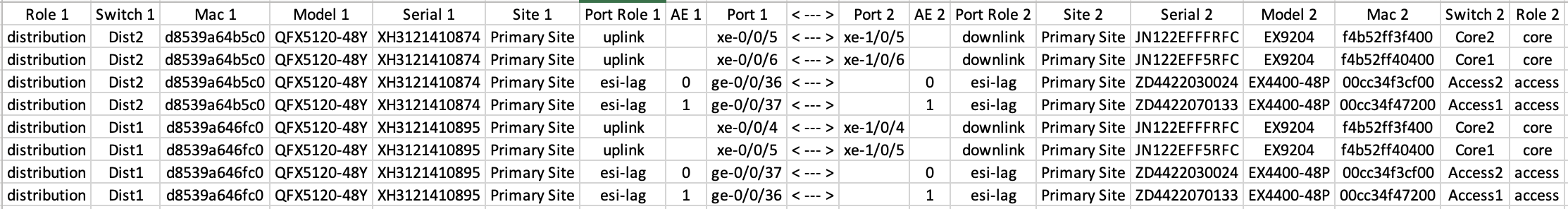
Connection Table spreadsheet:
Apply VLANs to Access ports
As previously discussed, Mist provides the ability to templatize well known services such as Radius, NTP (Network Time Protocol), DNS (Domain Name System), etc. that can be used across all devices within a Site. These templates can also include
VLANs and port profiles that can be targeted at each device within a Site. The last step before verification is to associate VLANs with the requisite ports on each Access switch.
In this case, Desktop1/2 are associated with different ports on each Access Switch which requires the configuration to be applied to Access1/2 respectively. Figure 10. Topology
It is also noteworthy that Mist Access Points connect to the same port on Access1/2 allowing the Switch Template to be customized with this configuration. For example, the following found under the Switch Template option is customized to associate each switch with its role: Core, Distribution, and Access. Further, all Access switches (defined by Model EX4400 as an example) associated the AP port profile with ge-0/0/16 without needing to configure each independent switch.
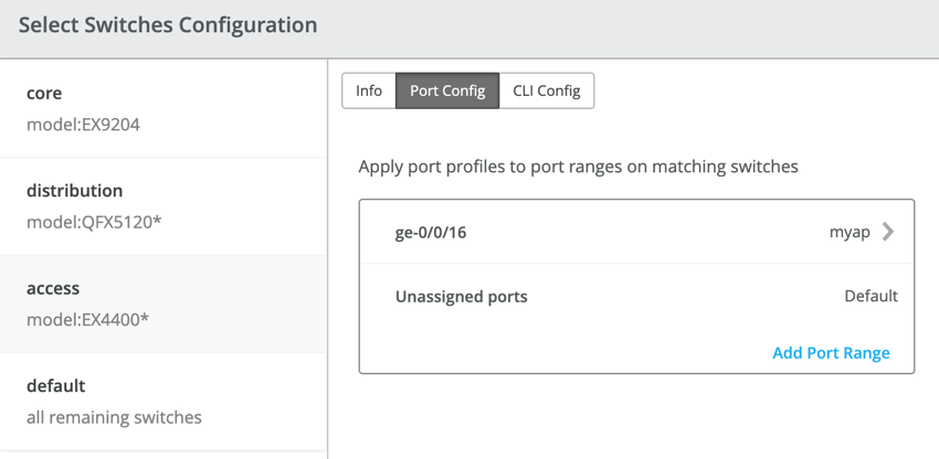
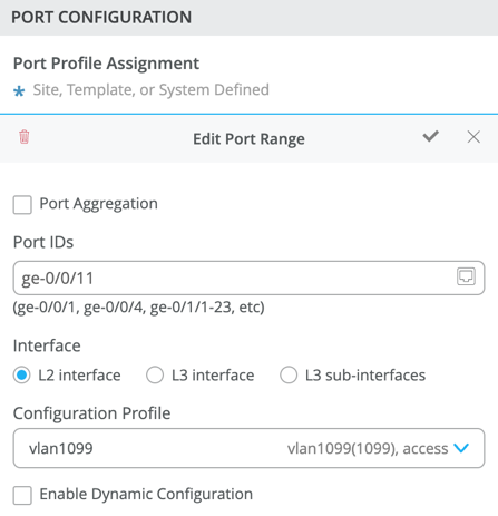
Using Access1 as an example, we apply vlan1099 to port ge-0/0/11 under the Port Configuration section on Access1. In this example, vlan1099 (corp-it), vlan1088 (developers), and vlan1033 (guest-wifi) are defined in the Switch Template. Here, vlan1099 is selected under the configuration profile:
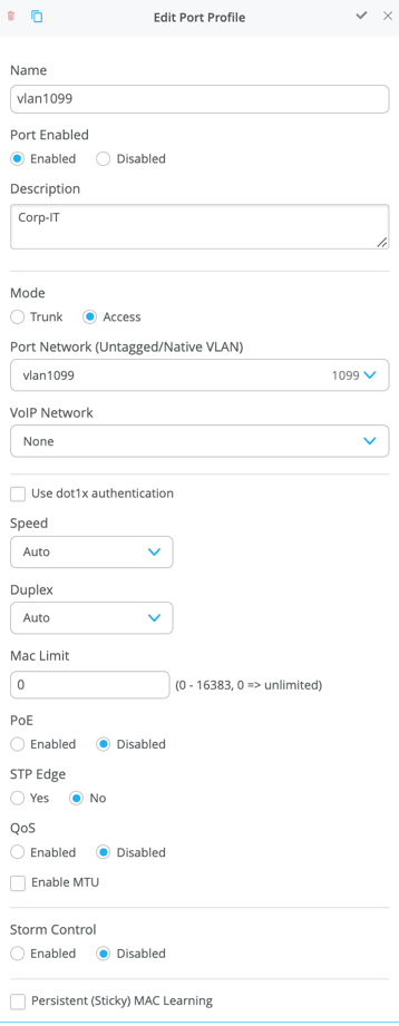
The Switch Template definition for vlan1099 is shown below, representing attributes associated with VLANs such as dot1x authentication, QoS (Quality of Service), and Power over Ethernet. Vlan1088 and vlan1033 will need to be configured in a similar fashion.
VERIFICATION
Verification of the Campus Fabric Core Distribution ERB deployment. Figure 10. Topology Currently there are two desktops that can be used to validate the fabric. Let us take a quick look to see if Desktop1 can connect internally and externally.
Validation steps
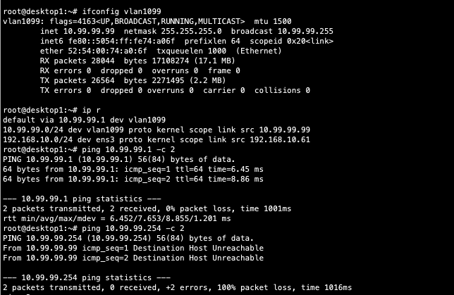
- Confirmed local IP address, vlan and default gateway were configured on Desktop1
- Can ping default gateway – that tells us we can reach access switch
- Ping to WAN router failed (10.99.99.254) – we need to troubleshoot.
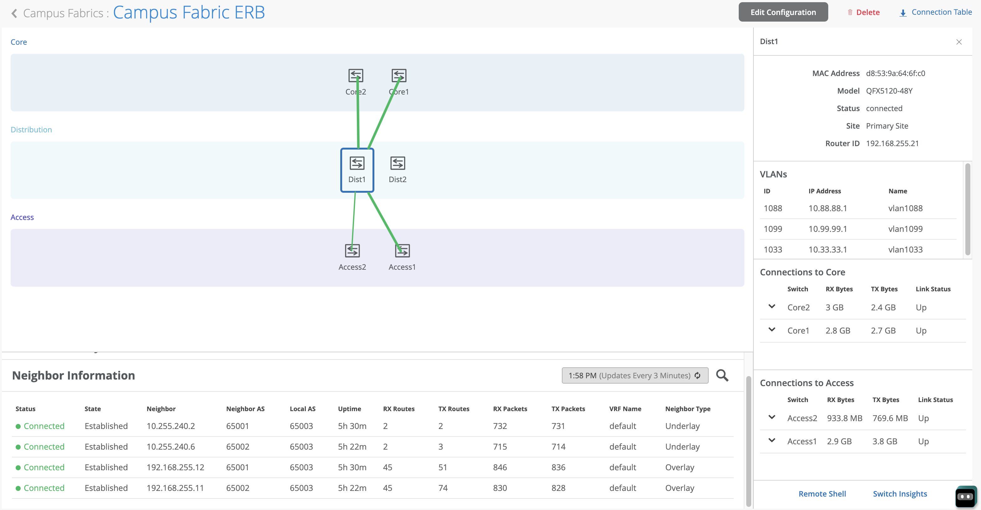
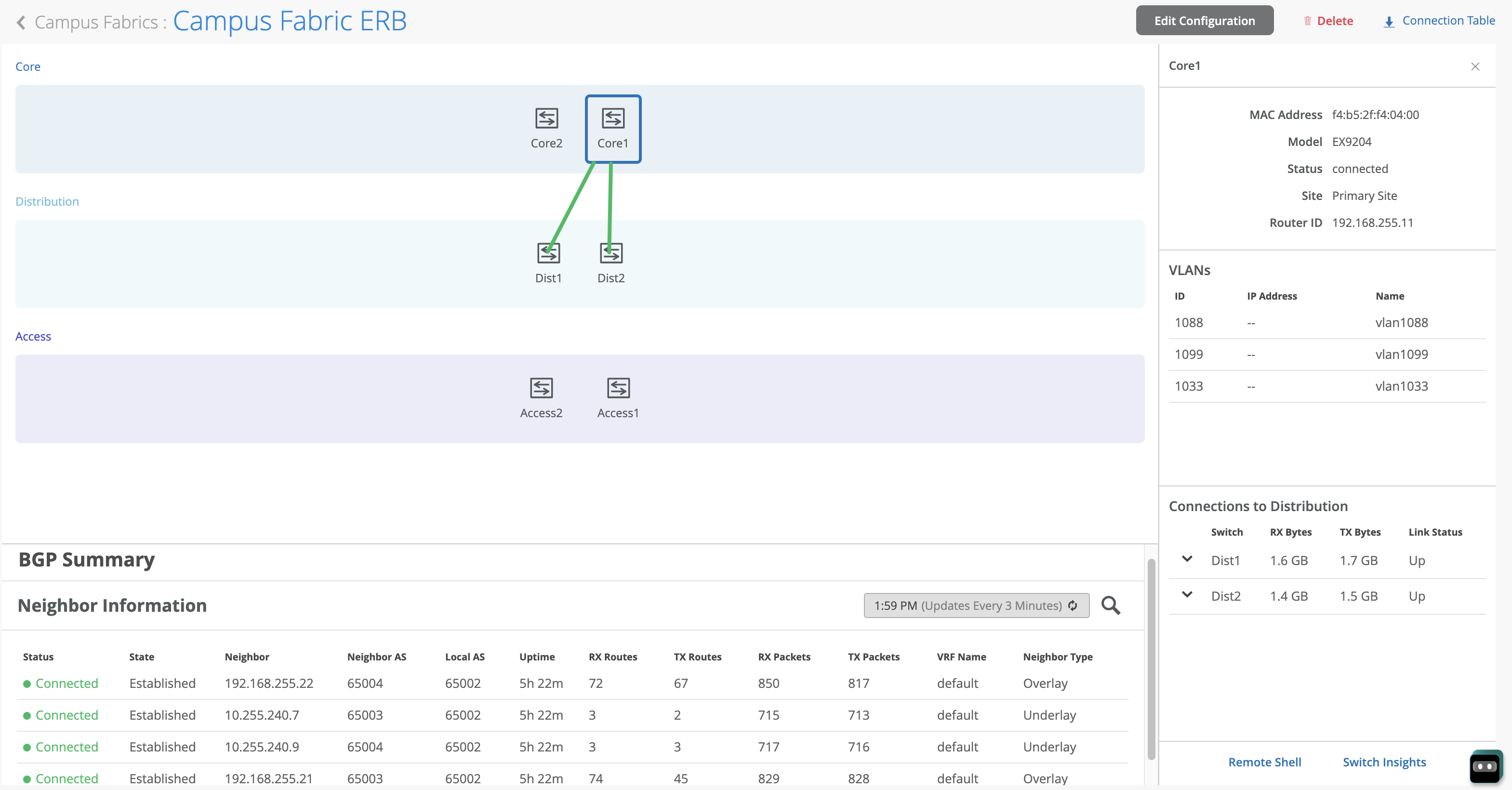
Start by validating Campus Fabric in the Mist UI, by selecting the Campus Fabric option under the Organization tab on the left-hand side of the UI.
Remote shell access into each device within the Campus Fabric is supported here as well as visual representation of the following capabilities:
- BGP peering establishment
- Transmit/Receive traffic on a link-by-link basis
- Telemetry, such as lldp, from each device that verifies the physical build
BGP Underlay
Purpose
Verifying the state of eBGP between Core and Distribution layers is essential for EVPN VXLAN to operate as expected. This network of point-to-point links between each layer supports:
- load balancing using ECMP for greater resiliency and bandwidth efficiencies.
- bfd, bi-directional forwarding, to decrease convergence times during failures
- loopback reachability to support VXLAN tunnelling
Without requiring verification at each layer, the focus can be on Dist1/2 and their eBGP relationships with Core1/2. If both Dist switches have “established” eBGP peering sessions with both Core switches, the user can move to the next phase of verification.
Action
Verify that BGP sessions are established from Core devices with Dist devices to ensure loopback reachability, bfd session status, and load-balancing using ECMP.
Verification of BGP peering
Dist1:
Remote Shell can be accessed via the bottom right of the Campus Fabric, from the switch view or via SSH (Secure Shell).
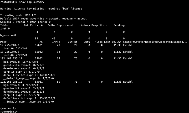
From the BGP summary we can see that the underlay (10.255.240.X) peer relationships are established tells us the underlay links are attached to the correct devices and the links are up.
It also shows the overlay (192.168.255.x) relationships are established and that it is peering at the correct loopback addresses. This demonstrates loopback reachability.
We can also see routes received; time established are roughly equal which looks good so far.
If BGP is not established then go back and validate the underlay links and addressing, and that the loopback addresses are correct. Loopback addresses should be pingable from other loopback addresses.
Verification of BGP connections can be performed on any of the other switches (not shown).
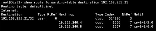
The primary goal of eBGP in the underlay is to provide loopback reachability between Core and Dist devices in the Campus Fabric. This loopback is used to terminate VXLAN tunnels between devices. The following shows loopback reachability from Dist1 to all devices in the Campus Fabric:
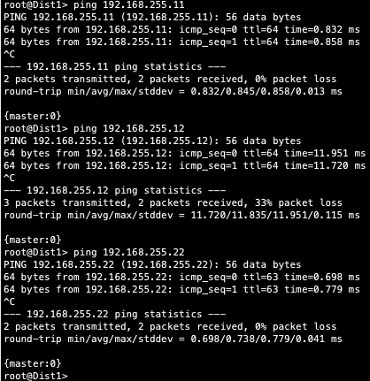
Let us verify the routes are established to the to the Core and other devices across multiple paths. For example, Dist1 should leverage both paths through Core1/2 to reach Dist2 and vice versa.
Dist1: ECMP Loopback reachability to Dist2 through Core1/2
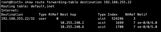
Dist2: ECMP Loopback reachability with Dist1 through Core1/2
This can be repeated for Core1/2 to verify ECMP load balancing
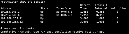
Finally, we validate BFD for fast converge in the case of a link or device failure:
EVPN VXLAN verification between Core and Distribution switches
Since the desktop can ping its default gateway, we can assume the ethernet-switching tables are correctly populated, vlan and interface-mode are correct. If pinging the default gateway failed, then troubleshoot underlay connectivity.
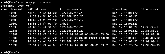
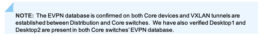
Verification of the EVPN Database on both Core switches
Core1:
Core2:
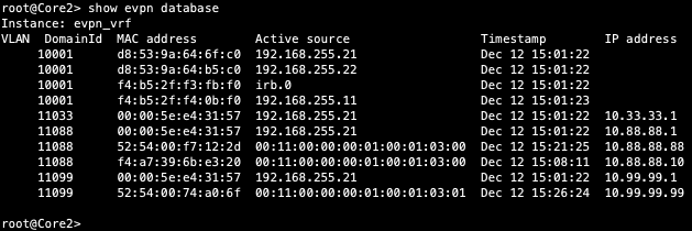
Both Core switches have identical EVPN databases which is expected. Notice the entries for desktop1 (10.99.99.99) and desktop2 (10.88.88.88) present in each Core switch. These entries are learned through the Campus Fabric from the ESI LAGs off DIst1/2.
10.99.99.99 is associated with irb.1099 and we see VNI of 11099. Let us just double check VLAN-VNI mapping on the Dist and Core switches and verify the presence of L3 on the Dist switches.
Dist
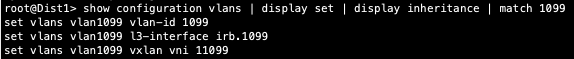
Core
![]()
We now know that there could be an issue with the config or status of the Core switches. The vlan configuration stanza does not show 1099 which points to lack of configuration on the Core devices. However, we still have control plane output that displays both desktop’s IP and MAC addresses. Let us keep troubleshooting.
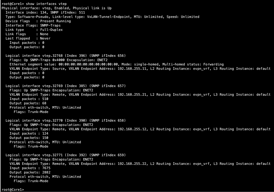
Verification of VXLAN tunnelling between Dist and Core switches
Dist1:
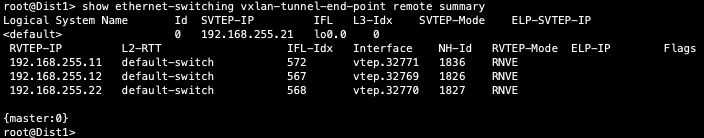
Core1:
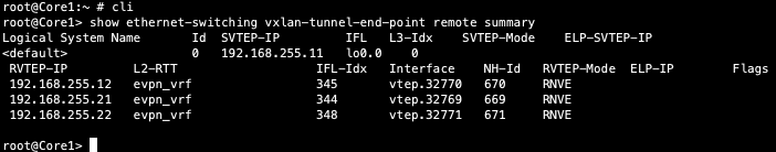
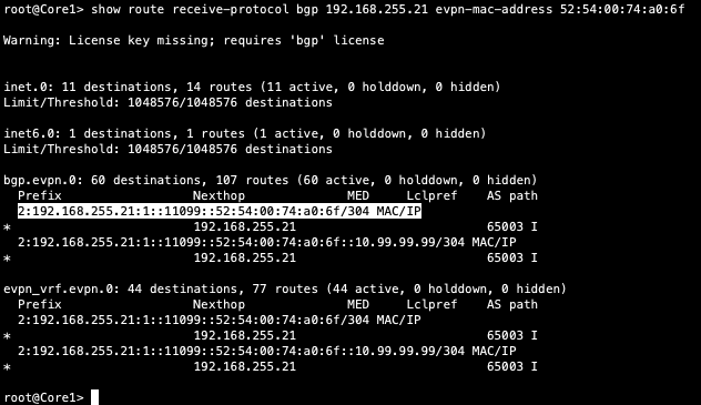
Finally, let us validate that Core1 is receiving Desktop 1’s MAC address through MP-BGP via Type2 EVPN routes:
We next verify if Desktop1’s MAC address is mapped to the correct VTEP interface on Core1:
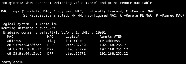
Notice, Core1 does not have Desktop1/s MAC address associated with the VXLAN tunnelling interface. This points back to the earlier comment regarding lack of configuration on the Core devices.
In other words, the Cores do not have VLAN visibility which they should since they act as a Border Router between the Campus Fabric EVPN VXLAN network and the northbound SRX firewall.
The Desktop’s ability to ping their default gateways located on the Distribution switches validate that level of connectivity. The next step is to determine why the Cores do not have the requisite VLAN configuration associated with the northbound SRX interfaces.
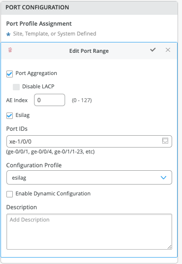
Notice Desktop1’s MAC address (52:54:00:74:a0:6f) is learned through both Dist1/2 switches
Core1 displays the vxlan tunnel endpoints in the ethernet switching table which validated control plane operational status. However, no endpoints are displayed in the ethernet switching table:
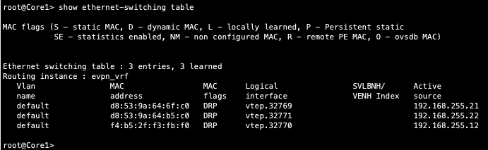
Dist1 does show both desktop MAC and ARP entries which once again validates control plane operational status within the Campus Fabric.
Connectivity between the Core and Dist switches looks correct since MAC and ARPs are being learned across the Fabric on both Dist switches. Why wouldn’t these VLANs shows up in the Core’s ethernet switching table? Let us look at the connection between Core and WAN router.
External Campus Fabric connectivity through the Border GW Core EX9204 switches
Remember that the user chose to deploy the Border GW capability on the EX9204 switches during the Campus Fabric Core-Distribution deployment, represented below:
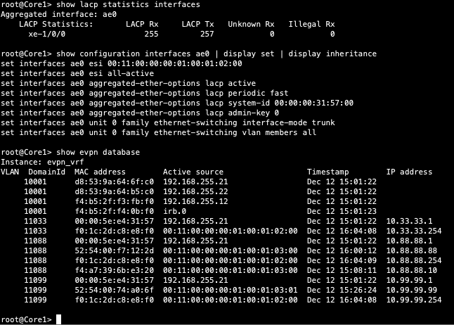
Mist enables the EX9204 to translate between VXLAN traffic within the Campus Fabric and standard ethernet switching for external connectivity, in this case a SRX firewall. Let us verify the ESI status on the Core switches.
![]()
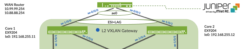
We forgot to configure the ESI-LAG: Mist does not configure this automatically. Add a Port profile on Core switches interfaces facing the WAN router.
The following represents an existing Port Profile applied to each SRX facing EX9204 port.
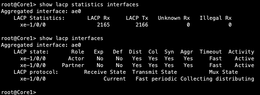
Save the config and then verify the changes on the Core switch.
Note that LACP is up (this infers there is an existing configuration on the SRX firewall.
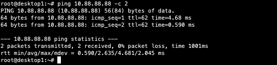
Then confirm the EVPN data base now has the ESI entry. The SRX IP address for each VLAN ending in .254 is also present in the evpn database. Back to Desktop1 to see if it can cross the fabric.
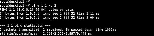
Last step is to verify Desktop1 can ping desktop2
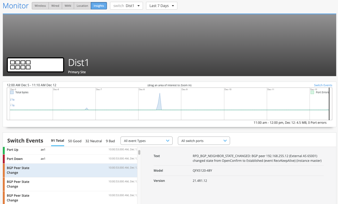
EVPN Insights
Mist Wired Assurance provides the user with real-time status related to the health of the Campus Fabric Core Distribution ERB deployment using telemetry such as BGP neighbor status and TX/RX port statistics. The following screenshots are taken from the Campus Fabric Core Distribution CRB build by accessing the Campus Fabric option under the Organization/Wired of the Mist Portal:
From this view, Mist also provides remote accessibility into each device’s console through the Remote Shell option as well as rich telemetry through the Switch Insights option. Remote Shell has been demonstrated throughout this document when displaying real-time operational status of each device during the verification stage.
Switch Insights of Dist1 displays historical telemetry including BGP peering status critical to the health of the Campus Fabric:
Summary
Mist Campus fabric provides an easy method to build a Core Distribution ERB to enable EVPN-VXLAN overlay networks. This can be done solely via Mist UI. Steps have been added to this document to help you understand the troubleshooting steps if deployment is not working correctly.
Appendix
Campus Fabric Core Distribution ERB Configurations
This section displays the configuration output from the Mist Cloud for the IP Fabric underlay on the core and distribution switches using eBGP.
Mist provides the user with the following options (default in parenthesis):
- BGP Local AS (65001)
- Loopback Prefix (/24)
- Subnet (10.255.240.0/20) – point to point interfaces between adjacent layers
Throughout the Campus Fabric between core and distribution layers, Mist enables per-packet (Junos defines this as per-flow) load-balancing using ECMP and fast convergence of BGP in the event of a link or node failure using BFD.
Core1 Configuration
- Interconnects between the two distribution switches
| set interfaces xe-1/0/5 description evpn_downlink-to-d8539a646fc0
set interfaces xe-1/0/5 unit 0 family inet address 10.255.240.6/31 set interfaces xe-1/0/6 description evpn_downlink-to-d8539a64b5c0 set interfaces xe-1/0/6 unit 0 family inet address 10.255.240.8/31 |
- Loopback interface and router ID
| set groups top interfaces lo0 unit 0 family inet address 192.168.255.11/32
set groups top routing-options router-id 192.168.255.11 |
- Per-packet load-balancing
| set groups top policy-options policy-statement ecmp_policy then load-balance per-packet
set groups top policy-options policy-statement ecmp_policy then accept set groups top routing-options forwarding-table export ecmp_policy |
- BGP underlay network between the two distribution switches
| set protocols bgp group evpn_underlay type external
set protocols bgp group evpn_underlay log-updown set protocols bgp group evpn_underlay import evpn_underlay_import set protocols bgp group evpn_underlay family inet unicast set protocols bgp group evpn_underlay authentication-key “$9$deboJGUHf5FwYfT36AtxN-V4ak.P5Fnbs4ZjHmPSrlvxNws4oGDY2n/9A1IxN-ws4ik.5z3q.z6CtIR24oJikFn/tpB6/u1RhKvgoaUk.mfTn6AzFyleK8LUjiHqf369pO1zFlK8X-ds24aJDik.PfzkqBIEhKvjHkq5QCtu0IEAtOREcvMaZGD.P” set protocols bgp group evpn_underlay export evpn_underlay_export set protocols bgp group evpn_underlay local-as 65002 set protocols bgp group evpn_underlay multipath multiple-as set protocols bgp group evpn_underlay bfd-liveness-detection minimum-interval 350 set protocols bgp group evpn_underlay bfd-liveness-detection multiplier 3 set protocols bgp group evpn_underlay neighbor 10.255.240.7 peer-as 65003 set protocols bgp group evpn_underlay neighbor 10.255.240.9 peer-as 65004 set protocols bgp graceful-restart |
Core2 Configuration
- Interconnects between the two distribution switches
| set interfaces xe-1/0/4 description evpn_downlink-to-d8539a646fc0
set interfaces xe-1/0/4 unit 0 family inet address 10.255.240.2/31 set interfaces xe-1/0/5 description evpn_downlink-to-d8539a64b5c0 set interfaces xe-1/0/5 unit 0 family inet address 10.255.240.4/31 |
- Loopback interface and router ID
| set groups top interfaces lo0 unit 0 family inet address 192.168.255.12/32
set groups top routing-options router-id 192.168.255.12 |
- Per-packet load-balancing
| set groups top policy-options policy-statement ecmp_policy then load-balance per-packet
set groups top policy-options policy-statement ecmp_policy then accept set groups top routing-options forwarding-table export ecmp_policy |
- BGP underlay network between the two distribution switches
| set protocols bgp group evpn_underlay type external
set protocols bgp group evpn_underlay log-updown set protocols bgp group evpn_underlay import evpn_underlay_import set protocols bgp group evpn_underlay family inet unicast set protocols bgp group evpn_underlay authentication-key “$9$71-24aJD.mTdb.PQF/98XxNYgjHqmTz-VYoGDkqEcSl8XdVY2aZbwz3n/0O8XxdVYUjHm5QiH5F69OBwY24UjTz39CuF3A0BIrls2gJjHk.PzF/5ThSyrvMJGUDi.QFnCp05TSrvWx7VwYg4ZUjHq.5jiuO1IrlGDjimf69AtO1/9pB1RlegoaZHq” set protocols bgp group evpn_underlay export evpn_underlay_export set protocols bgp group evpn_underlay local-as 65001 set protocols bgp group evpn_underlay multipath multiple-as set protocols bgp group evpn_underlay bfd-liveness-detection minimum-interval 350 set protocols bgp group evpn_underlay bfd-liveness-detection multiplier 3 set protocols bgp group evpn_underlay neighbor 10.255.240.3 peer-as 65003 set protocols bgp group evpn_underlay neighbor 10.255.240.5 peer-as 65004 set protocols bgp graceful-restart |
Dist1 Configuration
- Interconnects between the two core switches
| Core Interfaces:
set interfaces xe-0/0/4 description evpn_uplink-to-f4b52ff3f400 set interfaces xe-0/0/4 unit 0 family inet address 10.255.240.3/31 set interfaces xe-0/0/5 description evpn_uplink-to-f4b52ff40400 set interfaces xe-0/0/5 unit 0 family inet address 10.255.240.7/31 |
- Loopback interface and router ID
| set groups top interfaces lo0 unit 0 family inet address 192.168.255.21/32
set groups top routing-options router-id 192.168.255.21 |
- Per-packet load-balancing
| set groups top policy-options policy-statement ecmp_policy then load-balance per-packet
set groups top policy-options policy-statement ecmp_policy then accept set groups top routing-options forwarding-table export ecmp_policy |
- BGP underlay network between the two core switches
| set protocols bgp group evpn_underlay type external
set protocols bgp group evpn_underlay log-updown set protocols bgp group evpn_underlay import evpn_underlay_import set protocols bgp group evpn_underlay family inet unicast set protocols bgp group evpn_underlay authentication-key “$9$wLYZUji.Qz624QF/Cu0-VbsJGmfTz69YgJDk.5TlKv8-V2gJZjH4o9AtuEh-Vb2gJqmfzn/PfnCp0hcoJZUqm69A0ORCABEcyW8aZGimf5QF9Cun6evMWx7ikq.PQ/CtOIEn6vWxNbwgoJGUHqmfTQnmPRhSyW8k.mPz3p0B1hSu0IcSr8LGDjHfT” set protocols bgp group evpn_underlay export evpn_underlay_export set protocols bgp group evpn_underlay local-as 65003 set protocols bgp group evpn_underlay multipath multiple-as set protocols bgp group evpn_underlay bfd-liveness-detection minimum-interval 350 set protocols bgp group evpn_underlay bfd-liveness-detection multiplier 3 set protocols bgp group evpn_underlay neighbor 10.255.240.2 peer-as 65001 set protocols bgp group evpn_underlay neighbor 10.255.240.6 peer-as 65002 set protocols bgp graceful-restart |
Dist2 Configuration
- Interconnects between the two core switches
| Core Interfaces:
set interfaces xe-0/0/5 description evpn_uplink-to-f4b52ff3f400 set interfaces xe-0/0/5 unit 0 family inet address 10.255.240.5/31 set interfaces xe-0/0/6 description evpn_uplink-to-f4b52ff40400 set interfaces xe-0/0/6 unit 0 family inet address 10.255.240.9/31 |
- Loopback interface and router ID
| set groups top interfaces lo0 unit 0 family inet address 192.168.255.22/32
set groups top routing-options router-id 192.168.255.22 |
- Per-packet load-balancing
| set groups top policy-options policy-statement ecmp_policy then load-balance per-packet
set groups top policy-options policy-statement ecmp_policy then accept set groups top routing-options forwarding-table export ecmp_policy |
- BGP underlay network between the two core switches
| set protocols bgp group evpn_underlay type external
set protocols bgp group evpn_underlay log-updown set protocols bgp group evpn_underlay import evpn_underlay_import set protocols bgp group evpn_underlay family inet unicast set protocols bgp group evpn_underlay authentication-key “$9$GpDmfTQntpBjHtu1RSyoJZU.P69ApBIDi.5FnCA7-dwoJji.mTzHkIEhSMWoJZji.369pO1/9ORcyW8k.mf36BIEyrvRElM8XbwqmPQ69CtuIRSOBNdVb2gQF3n/t1RhrKMOBdb24ZGik.Pfz369AtO6/vWLXbwFn6/p0cyleWLSyK8LxwsP5Tz9A” set protocols bgp group evpn_underlay export evpn_underlay_export set protocols bgp group evpn_underlay local-as 65004 set protocols bgp group evpn_underlay multipath multiple-as set protocols bgp group evpn_underlay bfd-liveness-detection minimum-interval 350 set protocols bgp group evpn_underlay bfd-liveness-detection multiplier 3 set protocols bgp group evpn_underlay neighbor 10.255.240.4 peer-as 65001 set protocols bgp group evpn_underlay neighbor 10.255.240.8 peer-as 65002 set protocols bgp graceful-restart |
Configuration of the EVPN VXLAN Overlay and Virtual Networks
This section displays the configuration output from the Mist Cloud for the EVPN VXLAN Overlay on the core and distribution switches using eBGP.
Mist enables load balancing across the Overlay network and fast convergence of BGP in the event of a link or node failure using BFD between the core and distribution layers.
Mist provisions L3 IRB interfaces on the Distribution layer
Mist enables VXLAN tunnelling, VLAN to VXLAN mapping, and MP BGP configuration snippets such as vrf-targets on the distribution and core switches
VRFs for traffic isolation are provisioned on the distribution switches
Core1 Configuration
- BGP Overlay peering between the two distribution switches
| set protocols bgp group evpn_overlay type external
set protocols bgp group evpn_overlay multihop ttl 1 set protocols bgp group evpn_overlay multihop no-nexthop-change set protocols bgp group evpn_overlay local-address 192.168.255.11 set protocols bgp group evpn_overlay log-updown set protocols bgp group evpn_overlay family evpn signaling loops 2 set protocols bgp group evpn_overlay authentication-key “$9$deboJGUHf5FwYfT36AtxN-V4ak.P5Fnbs4ZjHmPSrlvxNws4oGDY2n/9A1IxN-ws4ik.5z3q.z6CtIR24oJikFn/tpB6/u1RhKvgoaUk.mfTn6AzFyleK8LUjiHqf369pO1zFlK8X-ds24aJDik.PfzkqBIEhKvjHkq5QCtu0IEAtOREcvMaZGD.P” set protocols bgp group evpn_overlay local-as 65002 set protocols bgp group evpn_overlay multipath multiple-as set protocols bgp group evpn_overlay bfd-liveness-detection minimum-interval 1000 set protocols bgp group evpn_overlay bfd-liveness-detection multiplier 3 set protocols bgp group evpn_overlay bfd-liveness-detection session-mode automatic set protocols bgp group evpn_overlay neighbor 192.168.255.21 peer-as 65003 set protocols bgp group evpn_overlay neighbor 192.168.255.22 peer-as 65004 |
- Switch options that define vrf-targets and the source loopback interface used for vxlan
| set groups top routing-instances evpn_vs vtep-source-interface lo0.0
set groups top routing-instances evpn_vs route-distinguisher 192.168.255.11:1 set groups top routing-instances evpn_vs vrf-target target:65000:1 |
- VXLAN encapsulation
| set groups top routing-instances evpn_vs protocols evpn encapsulation vxlan
set groups top routing-instances evpn_vs protocols evpn default-gateway no-gateway-community set groups top routing-instances evpn_vs protocols evpn extended-vni-list all |
- VLAN to VXLAN mapping
| set groups top routing-instances evpn_vs vlans vlan1033 vlan-id 1033
set groups top routing-instances evpn_vs vlans vlan1033 vxlan vni 11033 set groups top routing-instances evpn_vs vlans vlan1088 vlan-id 1088 set groups top routing-instances evpn_vs vlans vlan1088 vxlan vni 11088 set groups top routing-instances evpn_vs vlans vlan1099 vlan-id 1099 set groups top routing-instances evpn_vs vlans vlan1099 vxlan vni 11099 |
Core2 Configuration
- BGP Overlay peering between the two distribution switches
| set protocols bgp group evpn_overlay type external
set protocols bgp group evpn_overlay multihop ttl 1 set protocols bgp group evpn_overlay multihop no-nexthop-change set protocols bgp group evpn_overlay local-address 192.168.255.12 set protocols bgp group evpn_overlay log-updown set protocols bgp group evpn_overlay family evpn signaling loops 2 set protocols bgp group evpn_overlay authentication-key “$9$71-24aJD.mTdb.PQF/98XxNYgjHqmTz-VYoGDkqEcSl8XdVY2aZbwz3n/0O8XxdVYUjHm5QiH5F69OBwY24UjTz39CuF3A0BIrls2gJjHk.PzF/5ThSyrvMJGUDi.QFnCp05TSrvWx7VwYg4ZUjHq.5jiuO1IrlGDjimf69AtO1/9pB1RlegoaZHq” set protocols bgp group evpn_overlay local-as 65001 set protocols bgp group evpn_overlay multipath multiple-as set protocols bgp group evpn_overlay bfd-liveness-detection minimum-interval 1000 set protocols bgp group evpn_overlay bfd-liveness-detection multiplier 3 set protocols bgp group evpn_overlay bfd-liveness-detection session-mode automatic set protocols bgp group evpn_overlay neighbor 192.168.255.21 peer-as 65003 set protocols bgp group evpn_overlay neighbor 192.168.255.22 peer-as 65004
|
- Switch options that define vrf-targets and the source loopback interface used for vxlan
| set groups top routing-instances evpn_vs vtep-source-interface lo0.0
set groups top routing-instances evpn_vs route-distinguisher 192.168.255.12:1 set groups top routing-instances evpn_vs vrf-target target:65000:1 |
- VXLAN encapsulation
| set groups top routing-instances evpn_vs protocols evpn encapsulation vxlan
set groups top routing-instances evpn_vs protocols evpn default-gateway no-gateway-community set groups top routing-instances evpn_vs protocols evpn extended-vni-list all |
- VLAN to VXLAN mapping
| set groups top routing-instances evpn_vs vlans vlan1033 vlan-id 1033
set groups top routing-instances evpn_vs vlans vlan1033 vxlan vni 11033 set groups top routing-instances evpn_vs vlans vlan1088 vlan-id 1088 set groups top routing-instances evpn_vs vlans vlan1088 vxlan vni 11088 set groups top routing-instances evpn_vs vlans vlan1099 vlan-id 1099 set groups top routing-instances evpn_vs vlans vlan1099 vxlan vni 11099 |
- BGP Overlay peering between the two core switches
| set protocols bgp group evpn_overlay type external
set protocols bgp group evpn_overlay multihop ttl 1 set protocols bgp group evpn_overlay multihop no-nexthop-change set protocols bgp group evpn_overlay local-address 192.168.255.21 set protocols bgp group evpn_overlay log-updown set protocols bgp group evpn_overlay family evpn signaling loops 2 set protocols bgp group evpn_overlay authentication-key “$9$wLYZUji.Qz624QF/Cu0-VbsJGmfTz69YgJDk.5TlKv8-V2gJZjH4o9AtuEh-Vb2gJqmfzn/PfnCp0hcoJZUqm69A0ORCABEcyW8aZGimf5QF9Cun6evMWx7ikq.PQ/CtOIEn6vWxNbwgoJGUHqmfTQnmPRhSyW8k.mPz3p0B1hSu0IcSr8LGDjHfT” set protocols bgp group evpn_overlay local-as 65003 set protocols bgp group evpn_overlay multipath multiple-as set protocols bgp group evpn_overlay bfd-liveness-detection minimum-interval 1000 set protocols bgp group evpn_overlay bfd-liveness-detection multiplier 3 set protocols bgp group evpn_overlay bfd-liveness-detection session-mode automatic set protocols bgp group evpn_overlay neighbor 192.168.255.12 peer-as 65001 set protocols bgp group evpn_overlay neighbor 192.168.255.11 peer-as 65002 |
- Switch options that define vrf-targets and the source loopback interface used for vxlan
| set groups top switch-options vtep-source-interface lo0.0
set groups top switch-options route-distinguisher 192.168.255.21:1 set groups top switch-options vrf-target target:65000:1 |
- VXLAN encapsulation
| set groups top routing-instances evpn_vs protocols evpn encapsulation vxlan
set groups top routing-instances evpn_vs protocols evpn default-gateway no-gateway-community set groups top routing-instances evpn_vs protocols evpn extended-vni-list all |
- VRFs used for traffic isolation
| set groups top routing-instances guest-wifi instance-type vrf
set groups top routing-instances guest-wifi routing-options static route 0.0.0.0/0 next-hop 10.33.33.254 set groups top routing-instances guest-wifi routing-options multipath set groups top routing-instances guest-wifi routing-options auto-export set groups top routing-instances guest-wifi protocols evpn ip-prefix-routes advertise direct-nexthop set groups top routing-instances guest-wifi protocols evpn ip-prefix-routes encapsulation vxlan set groups top routing-instances guest-wifi protocols evpn ip-prefix-routes vni 15560868 set groups top routing-instances guest-wifi interface irb.1033 set groups top routing-instances guest-wifi route-distinguisher 192.168.255.21:103 set groups top routing-instances guest-wifi vrf-target target:65000:103 set groups top routing-instances guest-wifi vrf-table-label set groups top routing-instances developers instance-type vrf set groups top routing-instances developers routing-options static route 0.0.0.0/0 next-hop 10.88.88.254 set groups top routing-instances developers routing-options multipath set groups top routing-instances developers routing-options auto-export set groups top routing-instances developers protocols evpn ip-prefix-routes advertise direct-nexthop set groups top routing-instances developers protocols evpn ip-prefix-routes encapsulation vxlan set groups top routing-instances developers protocols evpn ip-prefix-routes vni 15600414 set groups top routing-instances developers interface irb.1088 set groups top routing-instances developers route-distinguisher 192.168.255.21:102 set groups top routing-instances developers vrf-target target:65000:102 set groups top routing-instances developers vrf-table-label set groups top routing-instances corp-it instance-type vrf set groups top routing-instances corp-it routing-options static route 0.0.0.0/0 next-hop 10.99.99.254 set groups top routing-instances corp-it routing-options multipath set groups top routing-instances corp-it routing-options auto-export set groups top routing-instances corp-it protocols evpn ip-prefix-routes advertise direct-nexthop set groups top routing-instances corp-it protocols evpn ip-prefix-routes encapsulation vxlan set groups top routing-instances corp-it protocols evpn ip-prefix-routes vni 11284517 set groups top routing-instances corp-it interface irb.1099 set groups top routing-instances corp-it route-distinguisher 192.168.255.21:101 set groups top routing-instances corp-it vrf-target target:65000:101 set groups top routing-instances corp-it vrf-table-label |
- VLAN to VXLAN mapping
| set vlans vlan1033 vlan-id 1033
set vlans vlan1033 l3-interface irb.1033 set vlans vlan1033 vxlan vni 11033 set vlans vlan1088 vlan-id 1088 set vlans vlan1088 l3-interface irb.1088 set vlans vlan1088 vxlan vni 11088 set vlans vlan1099 vlan-id 1099 set vlans vlan1099 l3-interface irb.1099 set vlans vlan1099 vxlan vni 11099 |
- L3 IRB interface enablement with anycast addressing
| set interfaces irb unit 1033 description vlan1033
set interfaces irb unit 1033 family inet mtu 9000 set interfaces irb unit 1033 family inet address 10.33.33.1/24 set interfaces irb unit 1033 mac 00:00:5e:e4:31:57 set interfaces irb unit 1088 description vlan1088 set interfaces irb unit 1088 family inet mtu 9000 set interfaces irb unit 1088 family inet address 10.88.88.1/24 set interfaces irb unit 1088 mac 00:00:5e:e4:31:57 set interfaces irb unit 1099 description vlan1099 set interfaces irb unit 1099 family inet mtu 9000 set interfaces irb unit 1099 family inet address 10.99.99.1/24 set interfaces irb unit 1099 mac 00:00:5e:e4:31:57 |
Dist2 Configuration
- BGP Overlay peering between the two core switches
| set protocols bgp group evpn_overlay type external
set protocols bgp group evpn_overlay multihop ttl 1 set protocols bgp group evpn_overlay multihop no-nexthop-change set protocols bgp group evpn_overlay local-address 192.168.255.22 set protocols bgp group evpn_overlay log-updown set protocols bgp group evpn_overlay family evpn signaling loops 2 set protocols bgp group evpn_overlay authentication-key “$9$GpDmfTQntpBjHtu1RSyoJZU.P69ApBIDi.5FnCA7-dwoJji.mTzHkIEhSMWoJZji.369pO1/9ORcyW8k.mf36BIEyrvRElM8XbwqmPQ69CtuIRSOBNdVb2gQF3n/t1RhrKMOBdb24ZGik.Pfz369AtO6/vWLXbwFn6/p0cyleWLSyK8LxwsP5Tz9A” set protocols bgp group evpn_overlay local-as 65004 set protocols bgp group evpn_overlay multipath multiple-as set protocols bgp group evpn_overlay bfd-liveness-detection minimum-interval 1000 set protocols bgp group evpn_overlay bfd-liveness-detection multiplier 3 set protocols bgp group evpn_overlay bfd-liveness-detection session-mode automatic set protocols bgp group evpn_overlay neighbor 192.168.255.12 peer-as 65001 set protocols bgp group evpn_overlay neighbor 192.168.255.11 peer-as 65002 |
- Switch options that define vrf-targets and the source loopback interface used for vxlan
| set groups top switch-options vtep-source-interface lo0.0
set groups top switch-options route-distinguisher 192.168.255.22:1 set groups top switch-options vrf-target target:65000:1 |
- VXLAN encapsulation
| set groups top protocols evpn encapsulation vxlan
set groups top protocols evpn default-gateway no-gateway-community set groups top protocols evpn extended-vni-list all |
- VRFs used for traffic isolation
| set groups top routing-instances guest-wifi instance-type vrf
set groups top routing-instances guest-wifi routing-options static route 0.0.0.0/0 next-hop 10.33.33.254 set groups top routing-instances guest-wifi routing-options multipath set groups top routing-instances guest-wifi routing-options auto-export set groups top routing-instances guest-wifi protocols evpn ip-prefix-routes advertise direct-nexthop set groups top routing-instances guest-wifi protocols evpn ip-prefix-routes encapsulation vxlan set groups top routing-instances guest-wifi protocols evpn ip-prefix-routes vni 15560868 set groups top routing-instances guest-wifi interface irb.1033 set groups top routing-instances guest-wifi route-distinguisher 192.168.255.22:103 set groups top routing-instances guest-wifi vrf-target target:65000:103 set groups top routing-instances guest-wifi vrf-table-label set groups top routing-instances developers instance-type vrf set groups top routing-instances developers routing-options static route 0.0.0.0/0 next-hop 10.88.88.254 set groups top routing-instances developers routing-options multipath set groups top routing-instances developers routing-options auto-export set groups top routing-instances developers protocols evpn ip-prefix-routes advertise direct-nexthop set groups top routing-instances developers protocols evpn ip-prefix-routes encapsulation vxlan set groups top routing-instances developers protocols evpn ip-prefix-routes vni 15600414 set groups top routing-instances developers interface irb.1088 set groups top routing-instances developers route-distinguisher 192.168.255.22:102 set groups top routing-instances developers vrf-target target:65000:102 set groups top routing-instances developers vrf-table-label set groups top routing-instances corp-it instance-type vrf set groups top routing-instances corp-it routing-options static route 0.0.0.0/0 next-hop 10.99.99.254 set groups top routing-instances corp-it routing-options multipath set groups top routing-instances corp-it routing-options auto-export set groups top routing-instances corp-it protocols evpn ip-prefix-routes advertise direct-nexthop set groups top routing-instances corp-it protocols evpn ip-prefix-routes encapsulation vxlan set groups top routing-instances corp-it protocols evpn ip-prefix-routes vni 11284517 set groups top routing-instances corp-it interface irb.1099 set groups top routing-instances corp-it route-distinguisher 192.168.255.22:101 set groups top routing-instances corp-it vrf-target target:65000:101 set groups top routing-instances corp-it vrf-table-label |
- VLAN to VXLAN mapping
| set vlans vlan1033 vlan-id 1033
set vlans vlan1033 l3-interface irb.1033 set vlans vlan1033 vxlan vni 11033 set vlans vlan1088 vlan-id 1088 set vlans vlan1088 l3-interface irb.1088 set vlans vlan1088 vxlan vni 11088 set vlans vlan1099 vlan-id 1099 set vlans vlan1099 l3-interface irb.1099 set vlans vlan1099 vxlan vni 11099 |
- L3 IRB interface enablement with anycast addressing
| set interfaces irb unit 1033 description vlan1033
set interfaces irb unit 1033 family inet mtu 9000 set interfaces irb unit 1033 family inet address 10.33.33.1/24 set interfaces irb unit 1033 mac 00:00:5e:e4:31:57 set interfaces irb unit 1088 description vlan1088 set interfaces irb unit 1088 family inet mtu 9000 set interfaces irb unit 1088 family inet address 10.88.88.1/24 set interfaces irb unit 1088 mac 00:00:5e:e4:31:57 set interfaces irb unit 1099 description vlan1099 set interfaces irb unit 1099 family inet mtu 9000 set interfaces irb unit 1099 family inet address 10.99.99.1/24 set interfaces irb unit 1099 mac 00:00:5e:e4:31:57 |
Configuration of the Layer 2 ESI-LAG between the distribution switches and the access switches
This section displays the configuration output from the Mist Cloud for the enablement of the Layer 2 ESI LAG between the distribution switches and access switches. This Mist profile enables all VLANs on the ethernet bundle with requisite ESI and LACP configuration options. From the perspective of the access switches, the ethernet bundle that is configured on the access layer views the ESI-LAG as a single MAC address with the same LACP system-id. This enables load hashing between distribution and access layers without requiring L2 loop free detection protocols such as RSTP (Rapid Spanning Tree Protocol).
Dist1 Configuration
- Interface association with the newly created ethernet bundle that includes ESI and LACP configuration
| set interfaces ae1 apply-groups erb-lag
set interfaces ae1 esi 00:11:00:00:00:01:00:01:03:01 set interfaces ae1 esi all-active set interfaces ae1 aggregated-ether-options lacp active set interfaces ae1 aggregated-ether-options lacp periodic fast set interfaces ae1 aggregated-ether-options lacp system-id 00:00:00:31:57:01 set interfaces ae1 aggregated-ether-options lacp admin-key 1
set groups crb-lag interfaces <*> mtu 9100 set groups crb-lag interfaces <*> unit 0 family ethernet-switching interface-mode trunk set groups crb-lag interfaces <*> unit 0 family ethernet-switching vlan members vlan1088 set groups crb-lag interfaces <*> unit 0 family ethernet-switching vlan members vlan1099 set groups crb-lag interfaces <*> unit 0 family ethernet-switching vlan members vlan1033
set interfaces ge-0/0/36 description esilag-to-00cc34f3cf00 set interfaces ge-0/0/36 hold-time up 120000 set interfaces ge-0/0/36 hold-time down 1 set interfaces ge-0/0/36 ether-options 802.3ad ae1 set interfaces ge-0/0/37 description esilag-to-00cc34f3cf00 set interfaces ge-0/0/37 hold-time up 120000 set interfaces ge-0/0/37 hold-time down 1 set interfaces ge-0/0/37 ether-options 802.3ad ae0 |
Dist2 Configuration
- Interface association with the newly created ethernet bundle that includes ESI and LACP configuration
| set interfaces ae1 apply-groups erb-lag
set interfaces ae1 esi 00:11:00:00:00:01:00:01:03:01 set interfaces ae1 esi all-active set interfaces ae1 aggregated-ether-options lacp active set interfaces ae1 aggregated-ether-options lacp periodic fast set interfaces ae1 aggregated-ether-options lacp system-id 00:00:00:31:57:01 set interfaces ae1 aggregated-ether-options lacp admin-key 1
set groups crb-lag interfaces <*> mtu 9100 set groups crb-lag interfaces <*> unit 0 family ethernet-switching interface-mode trunk set groups crb-lag interfaces <*> unit 0 family ethernet-switching vlan members vlan1088 set groups crb-lag interfaces <*> unit 0 family ethernet-switching vlan members vlan1099 set groups crb-lag interfaces <*> unit 0 family ethernet-switching vlan members vlan1033
set interfaces ge-0/0/36 description esilag-to-00cc34f3cf00 set interfaces ge-0/0/36 hold-time up 120000 set interfaces ge-0/0/36 hold-time down 1 set interfaces ge-0/0/36 ether-options 802.3ad ae1 set interfaces ge-0/0/37 description esilag-to-00cc34f3cf00 set interfaces ge-0/0/37 hold-time up 120000 set interfaces ge-0/0/37 hold-time down 1 set interfaces ge-0/0/37 ether-options 802.3ad ae0 |
Access1 Configuration
- VLANs associated with the new LACP ethernet bundle
| set groups crb-lag interfaces <*> mtu 9100
set groups crb-lag interfaces <*> unit 0 family ethernet-switching interface-mode trunk set groups crb-lag interfaces <*> unit 0 family ethernet-switching vlan members vlan1088 set groups crb-lag interfaces <*> unit 0 family ethernet-switching vlan members vlan1099 set groups crb-lag interfaces <*> unit 0 family ethernet-switching vlan members vlan1033
set interfaces ae1 apply-groups erb-lag set interfaces ae1 aggregated-ether-options lacp active
set interfaces ge-0/0/36 ether-options 802.3ad ae1 set interfaces ge-0/0/37 ether-options 802.3ad ae1 |
Access2 Configuration
- VLANs associated with the new LACP ethernet bundle
| set groups crb-lag interfaces <*> mtu 9100
set groups crb-lag interfaces <*> unit 0 family ethernet-switching interface-mode trunk set groups crb-lag interfaces <*> unit 0 family ethernet-switching vlan members vlan1088 set groups crb-lag interfaces <*> unit 0 family ethernet-switching vlan members vlan1099 set groups crb-lag interfaces <*> unit 0 family ethernet-switching vlan members vlan1033
set interfaces ae1 apply-groups erb-lag set interfaces ae1 aggregated-ether-options lacp active
set interfaces ge-0/0/36 ether-options 802.3ad ae1 set interfaces ge-0/0/37 ether-options 802.3ad ae1 |
Configuration of the Layer 2 ESI-LAG between the core switches and SRX firewall
This section displays the configuration output from the Mist Cloud for the enablement of the Layer 2 ESI LAG between the core switches and SRX firewall. This Mist profile enables all VLANs on the ethernet bundle with requisite ESI and LACP configuration options. From the perspective of the SRX firewall, the ethernet bundle that is configured on the SRX views the ESI-LAG as a single MAC address with the same LACP system-id. This enables load hashing between the core and SRX without requiring L2 loop free detection protocols such as RSTP.
Core 1 Configuration
- Interface association with the newly created ethernet bundle that includes ESI and LACP configuration
| set interfaces xe-1/0/0 hold-time up 120000
set interfaces xe-1/0/0 hold-time down 1 set interfaces xe-1/0/0 ether-options 802.3ad ae1 set interfaces xe-1/0/0 unit 0 family ethernet-switching storm-control default
set interfaces ae1 apply-groups esilag set interfaces ae1 esi 00:11:00:00:00:01:00:01:02:01 set interfaces ae1 esi all-active set interfaces ae1 aggregated-ether-options lacp active set interfaces ae1 aggregated-ether-options lacp periodic fast set interfaces ae1 aggregated-ether-options lacp system-id 00:00:00:31:57:01 set interfaces ae1 aggregated-ether-options lacp admin-key 1 |
Core 2 Configuration
- Interface association with the newly created ethernet bundle that includes ESI and LACP configuration
| set interfaces xe-1/0/0 hold-time up 120000
set interfaces xe-1/0/0 hold-time down 1 set interfaces xe-1/0/0 ether-options 802.3ad ae1 set interfaces xe-1/0/0 unit 0 family ethernet-switching storm-control default
set interfaces ae1 apply-groups esilag set interfaces ae1 esi 00:11:00:00:00:01:00:01:02:01 set interfaces ae1 esi all-active set interfaces ae1 aggregated-ether-options lacp active set interfaces ae1 aggregated-ether-options lacp periodic fast set interfaces ae1 aggregated-ether-options lacp system-id 00:00:00:31:57:01 set interfaces ae1 aggregated-ether-options lacp admin-key 1 |
SRX Firewall Configuration
- Interface association with newly created ethernet bundle and LACP configuration
| set interfaces ae0 apply-groups lan
set interfaces ae0 flexible-vlan-tagging set interfaces ae0 mtu 9014 set interfaces ae0 aggregated-ether-options lacp active set interfaces ae0 unit 1033 description vlan1033 set interfaces ae0 unit 1033 vlan-id 1033 set interfaces ae0 unit 1033 family inet address 10.33.33.254/24 set interfaces ae0 unit 1088 description vlan1088 set interfaces ae0 unit 1088 vlan-id 1088 set interfaces ae0 unit 1088 family inet address 10.88.88.254/24 set interfaces ae0 unit 1099 description vlan1099 |